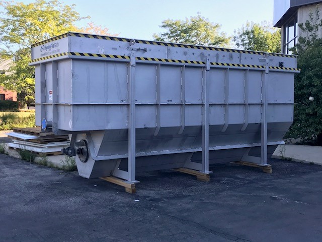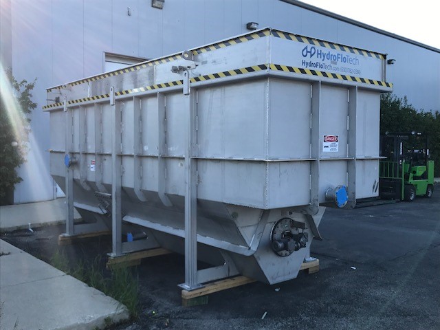

MaxiSep
There are many considerations to be taken into account when designing an enhanced gravity oil/water separator. The following needs to be taken into account as a minimum:
- Inlet flow distribution
- Length to height to width ratios (for proper overall flow distribution)
- Cross sectional velocities (actual, not nominal)
- Laminar flow conditions
- DynaPac™ Cross Corrugated coalescing media or parallel plate media “Reynolds” calculations (for quiescent flow distribution)
- Effluent flow distribution
- Total projected surface area
These basic design considerations all contribute to the complete utilization of the separation media. If followed properly, the results will be consistent, equal flow distribution through the separation chamber and the media pack. These are the earmarks of a thoughtful, wholly engineered, fully developed oil/water separator design.
The HydroFloTech oil water separators are considered the benchmark by which all others are judged. The design is constantly iterated and total attention is provided to every detail of the separators design. The fact that many of our peers in the industry have blatantly “borrowed” our design, speaks to the effectiveness of HydroFloTech design.
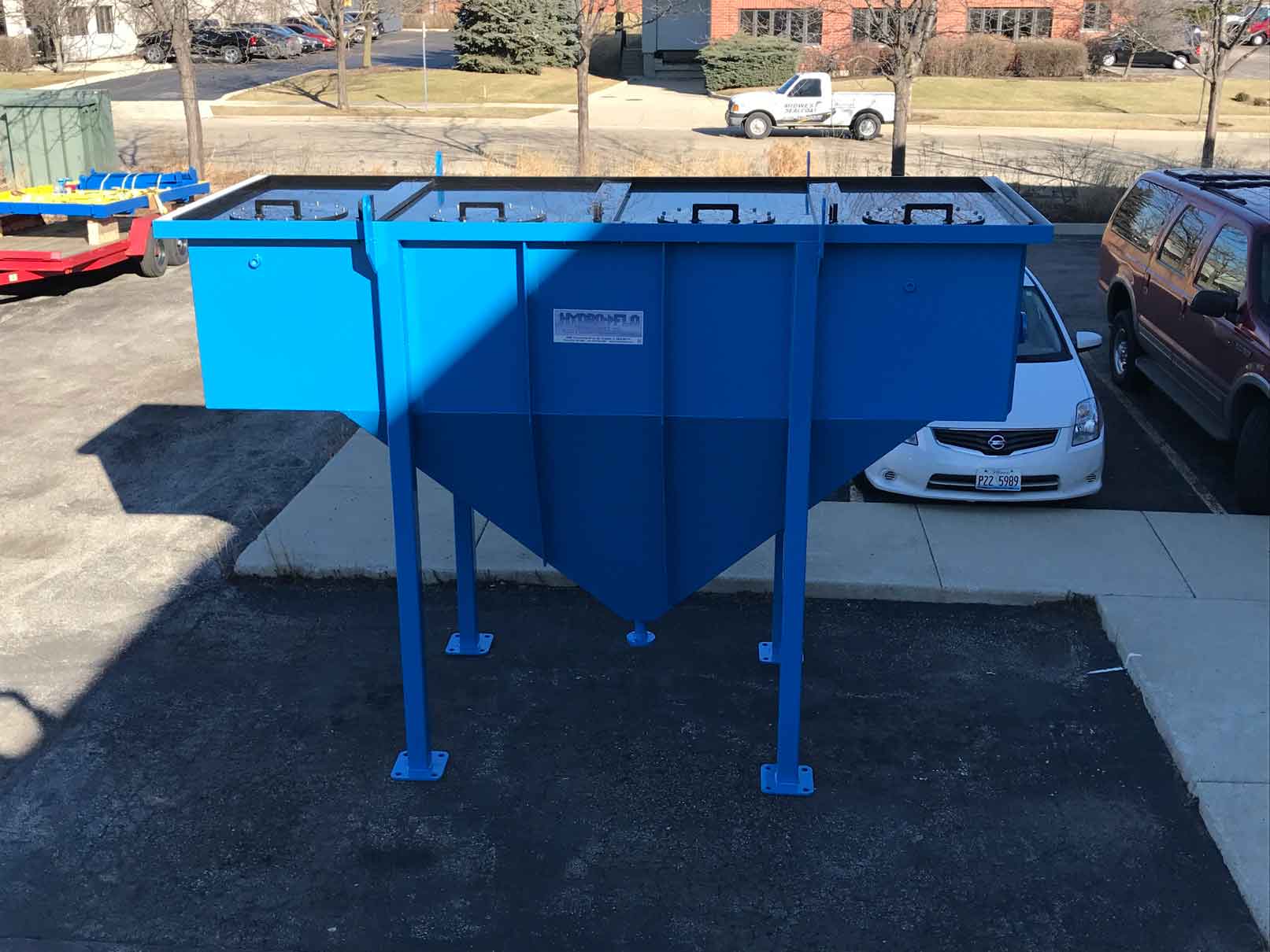
The separation cell is designed using elements of American Petroleum Institute’s publication 421 Feb. 1990 “Design of Oil-Water Separators” to ensure the best possible use of particle rise rate performance. The separation cell is a rectangular flat bottom tank manufactured from 304 stainless steel with an effluent surface baffle, 304 stainless steel full width adjustable overflow weir, effluent collection chamber with flanged outlet nozzle and recycle suction port, and angled float beaching plate.
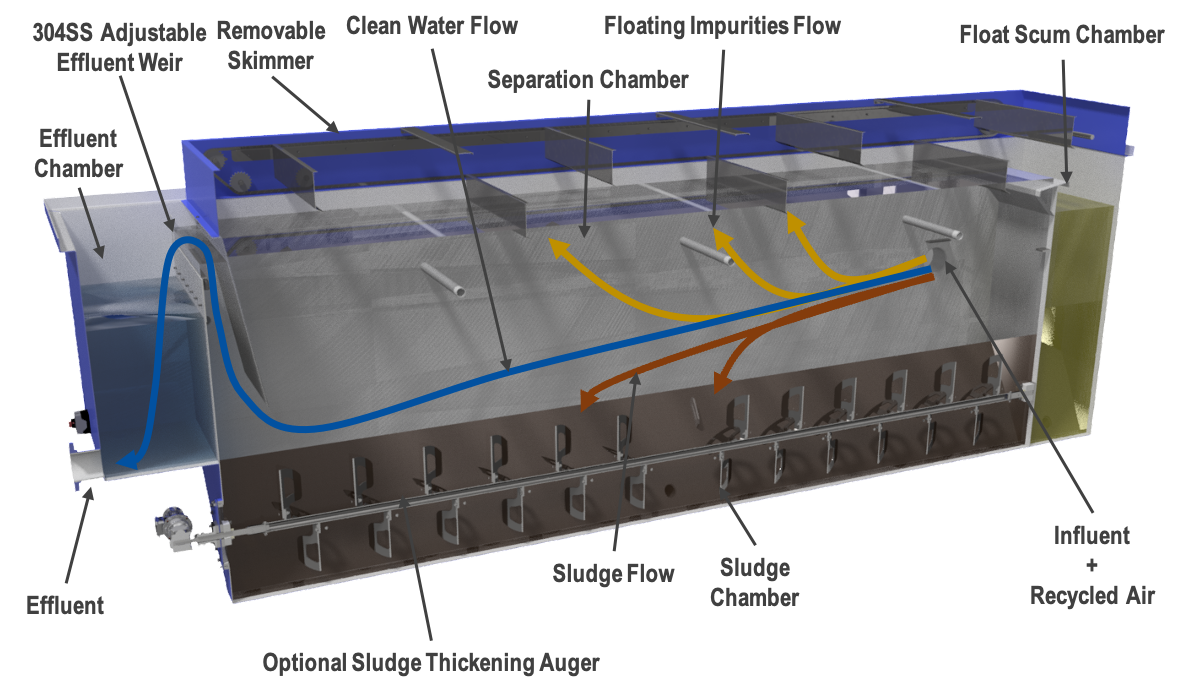
- Influent Diffusion Chamber
The flow enters the separator submerged, through an influent dispersion baffle. Dispersion across the depth and width of the DYNAPAC™ is achieved through the use of a non-clog diffuser. Heavy solids that fall out of suspension here are channeled to the sludge collection chamber. - Separation Chamber
The Separation Chamber is designed to fit the exact amount of DynaPac™ cross corrugated coalescing media, sized for specific applications. Adequate space is to be left before and after the chamber to prevent short circuiting through the pack. DynaPacTM coalescing media is available in 0.50”, 0.75” and 1.25” sizes all in PVC, H-PVC, Polypropylene or 304 stainless steel. Depending on the correct sizing of the unit, this media (sized in cubic feet) provides the correct surface area (in square feet) for ideal separation. HydroFloTech oil water separator sizing sheets are a great resource to determine the size of media required by application. - Sludge Collection Chamber
The sludge collection chamber is located directly beneath the coalescing media pack and provides ample storage capacity for the settled sludge. - Oil Discharge
The oil discharge port is located at the influent end of the separation chamber and incorporates an angled float/oil skimming plate. - Effluent Chamber
The aqueous phase leaving the DynaPac™ passes under the oil retention baffle and up over the adjustable 304 stainless steel effluent weir, which maintains the liquid level throughout the separator. - Removable Lids
The entire separator is typically covered with bolt down removable lid. - Coalescing Media
The coalescing media pack is fabricated of oleophilic cross corrugated coalescing media manufactured by HydroFloTech. - Surface Skimmer (Optional):
HydroFloTech provides a removable float skimming system with frame assembly and drive motor, sprockets, chains and full width stainless steel skimming blades. The skimmer blades are mounted on swivel pins that are fastened to the skimmer chains, which maintain the blades in a down position at all times. The conveyer chains are provided with drive sprockets on a full width shaft at the drive end and four independent idler sprockets at the return end. The skimmer system frame comes equipped with a sprocket tension adjustment device and the carrying and return tracks for the chain. The entire system is self supporting with side and end channels, and cross members with lifting lugs that permit removal of the skimmer assembly as a complete unit for easy cleaning and service. The skimmer drive system comes with a hollow shaft, maintenance free gear reducer. The skimmer system can be made vapor tight with the addition of optional cover panel. - Integrated Mechanical Sludge Thickener(Optional)
The bottom sludge thickening auger is designed to turn/fold the sludge over (at a relatively slow rate) and conveying the sludge to a central discharge point (as opposed to stirring/turning the material in a single direction) results in a more consistent, less stratified sludge blanket. As the sludge compresses/thickens toward the center of the thickener and along the thickener’s compressing edge, water passes up into the clarifier at the thickeners ends and at its rising edge homogenize and dewater sludge and grit as it moves it to a central convergence point, where it freely flows out the sludge outlet nozzle. Our unique design allows us to use less HP drive mechanism because of the smaller overall diameter. The drive mechanism is attached directly to the thickener with a removable safety cover. The auger is accessible by submerged bolt-on manway with Buna-N gasket material.
The sludge collection area can be designed where a sludge thickening auger may be added at a later point in time. - Control Package:
All HydroFloTech MaxiSep oil water separator with dissolved air flotation systems are fully automated. Control packages (depending on your specific requirements) are available in either basic relay logic control, or a fully state of the art PLC with touch screen HMI and our sophisticated treatment algorithms. The relay logic controls package allow basic reconfiguration of the original system settings, while the PLC based package allows maximum flexibility to change the process parameters, as well as tight control that minimizes chemical usage. All enclosures are NEMA 4x.
| Equipment Designing Data & Sizing Sheet Calculations | Drawings | Specifications | Installation, Operation & Maintenance Manual |
|---|---|---|---|
| Oil/Water Separator Theory of Operation | MaxiSep General Arrangement Drawing | “Common” Engineering Specification | MaxiSep Standard IO&M |
| Oil/Water Separator Design Parameters | General IO&M Considerations Applicable to all HydroFlo Manufactured Equipment | ||
| Oil Water Separator Test for Determination of Susceptibility of Separation |