
TotlSep
Standard Features
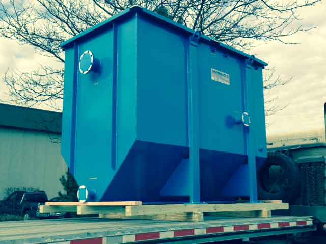
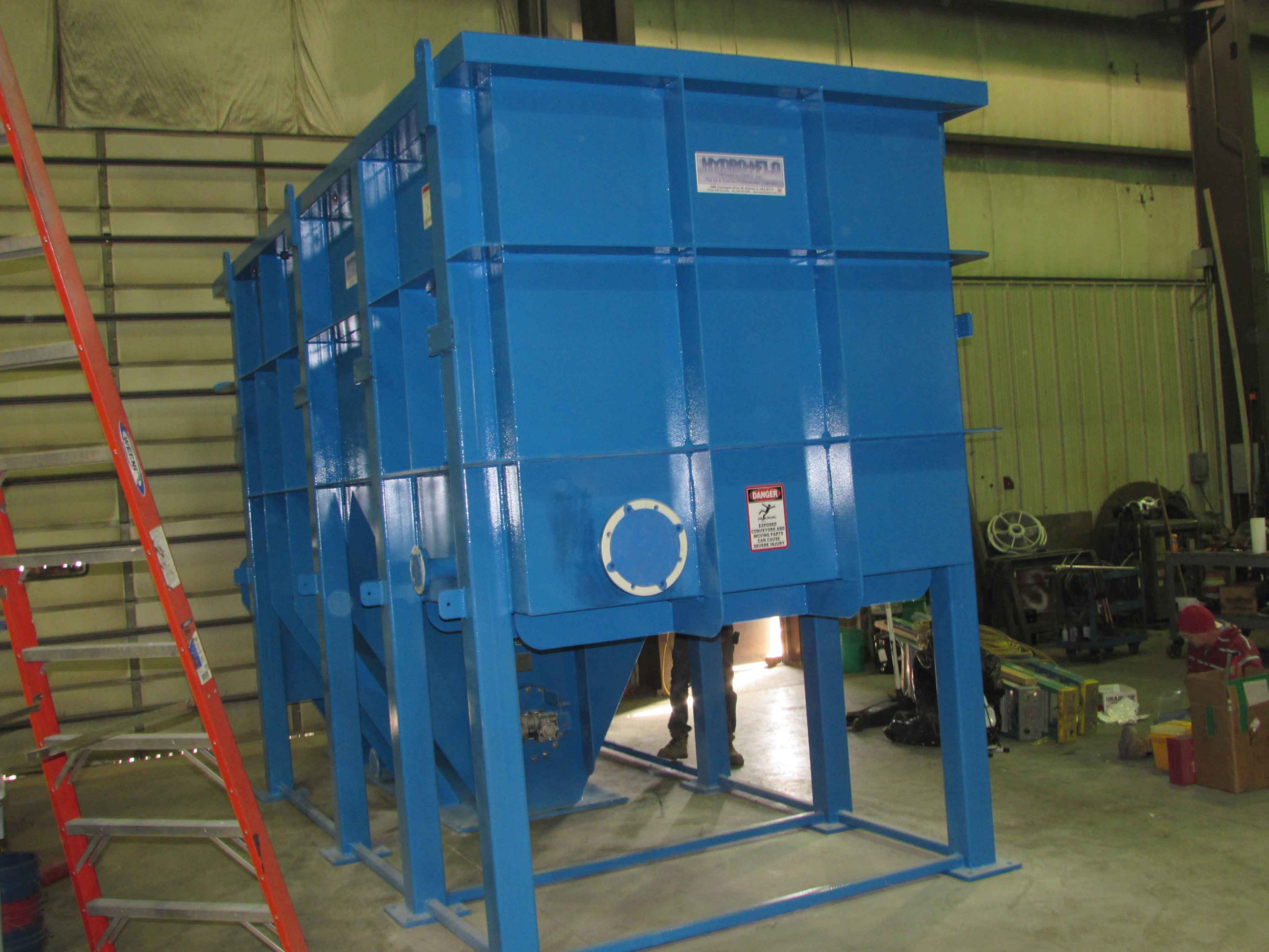
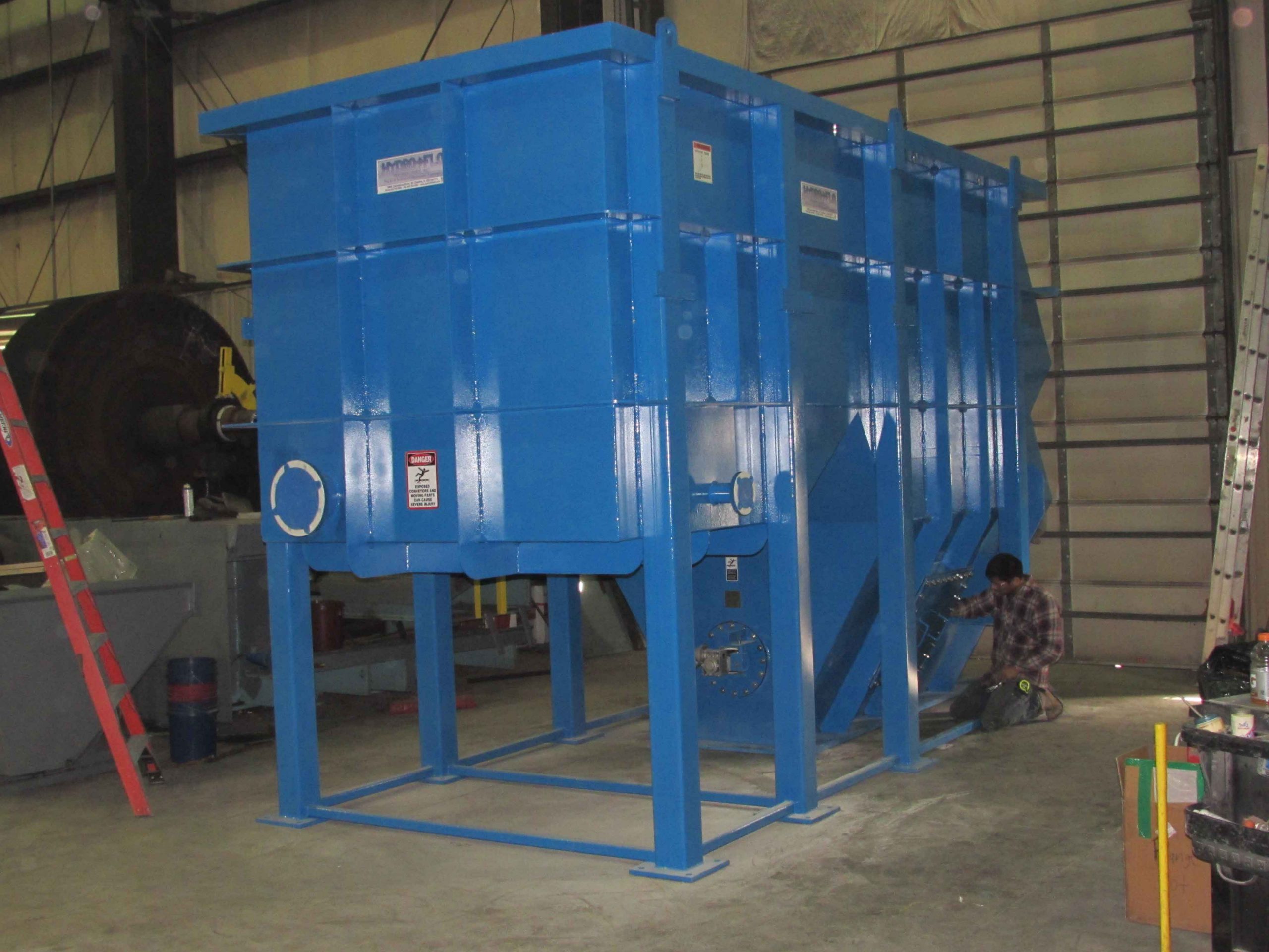
- Epoxy coated ASTM A-36 carbon steel tank
- Proprietary DynaPacTM hi-density PVC coalescing media
- Influent dispersion baffle
- Oil retention baffle specifically designed to enhance the performance of the DynaPacTM media
- Adjustable effluent weir system
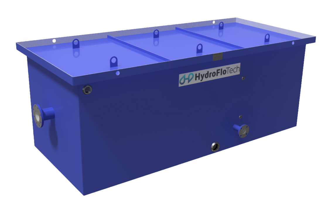
- Removable lid assembly
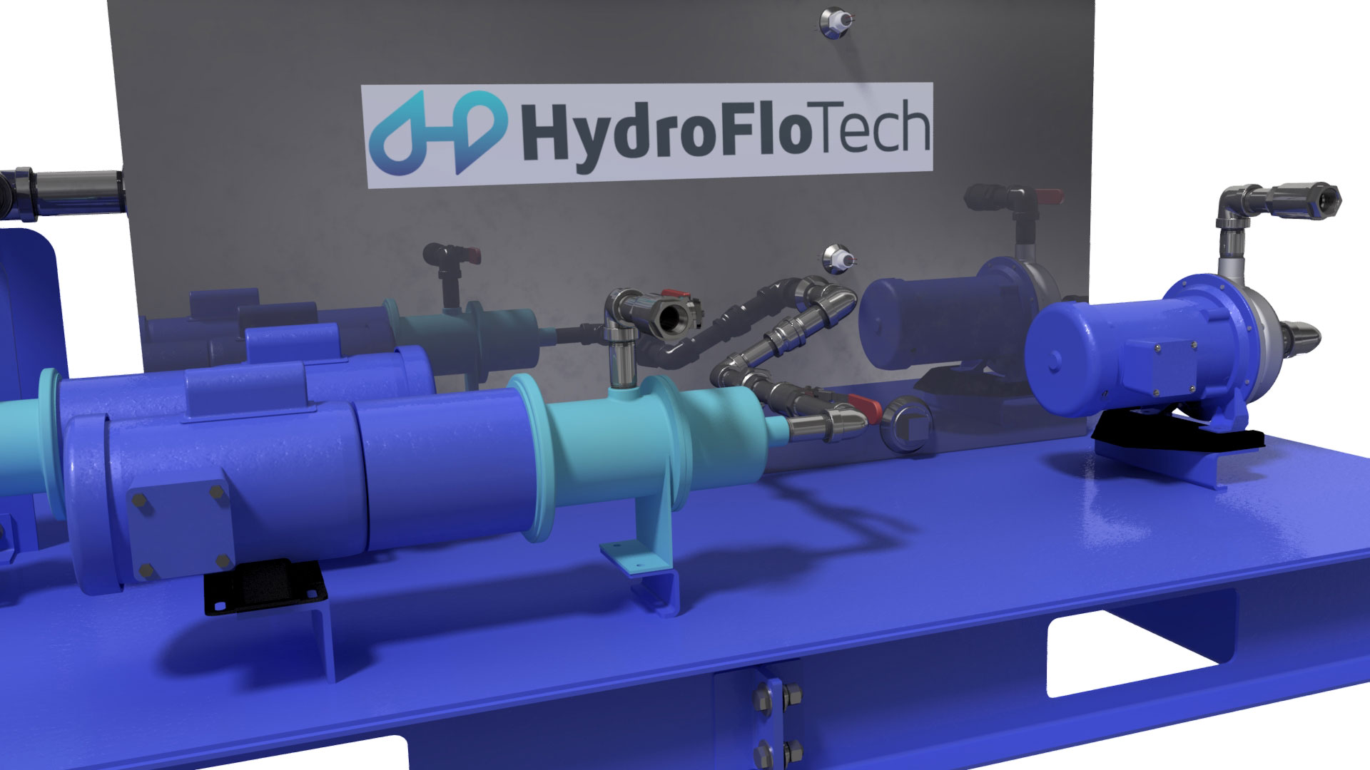
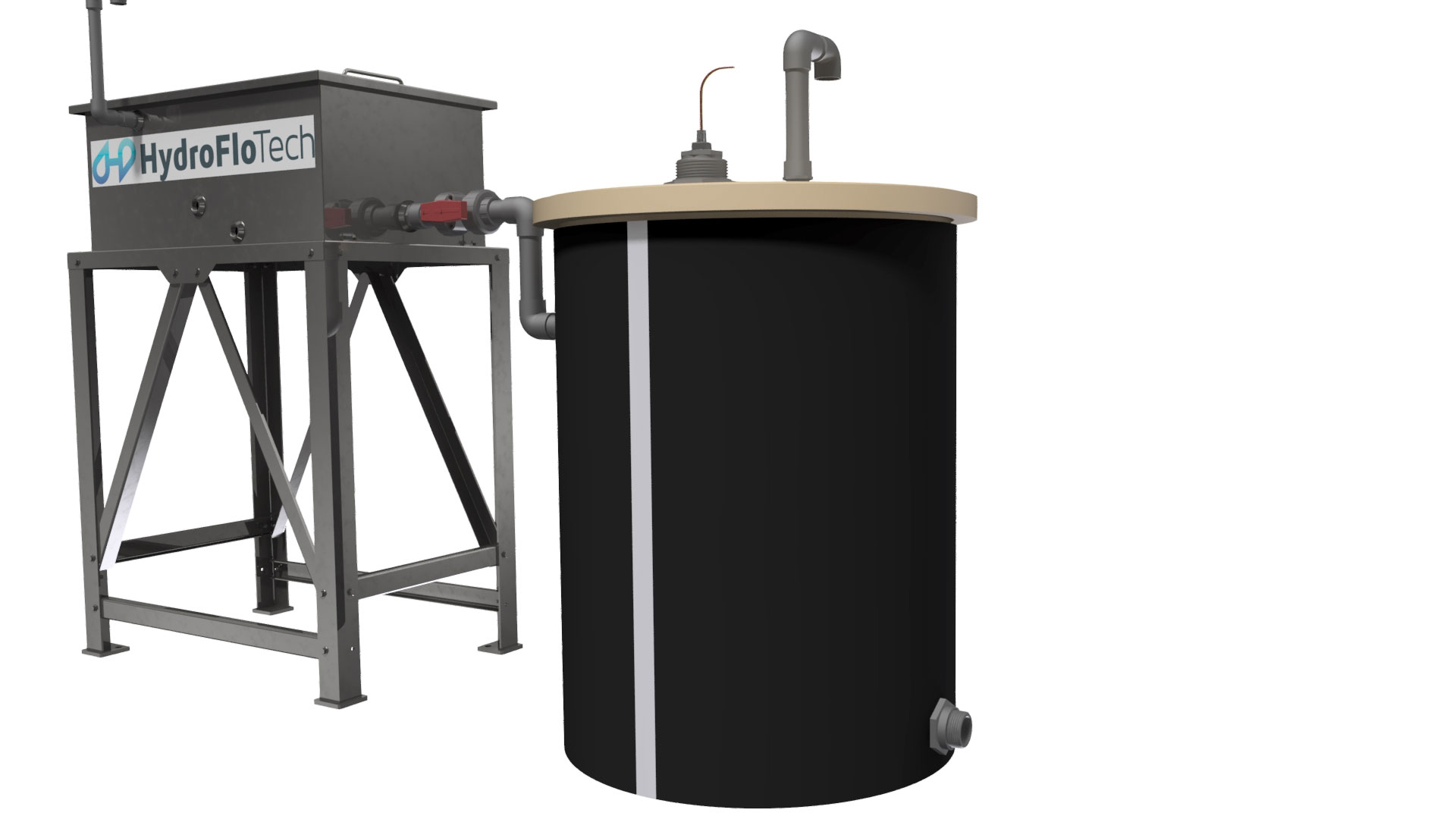
- Seamlessly integrates with other HydroFloTech wastewater products
Available Options
There are many considerations to be taken into account when designing an enhanced gravity oil water separator. The following needs to be taken into account as a minimum:
- Inlet flow distribution
- Length to height to width ratios (for proper overall flow distribution)
- Cross sectional velocities (actual, not nominal)
- Laminar flow conditions
- DynaPac™ Cross Corrugated coalescing media or parallel plate media “Reynolds” calculations (for quiescent flow distribution)
- Effluent flow distribution
- Total projected surface area
These basic design considerations all contribute to the complete utilization of the separation media. Follow them properly and the results will be consistent, equal flow distribution through the separation chamber and the media pack. These are the earmarks of a thoughtful, wholly engineered, fully developed oil/water separator design.
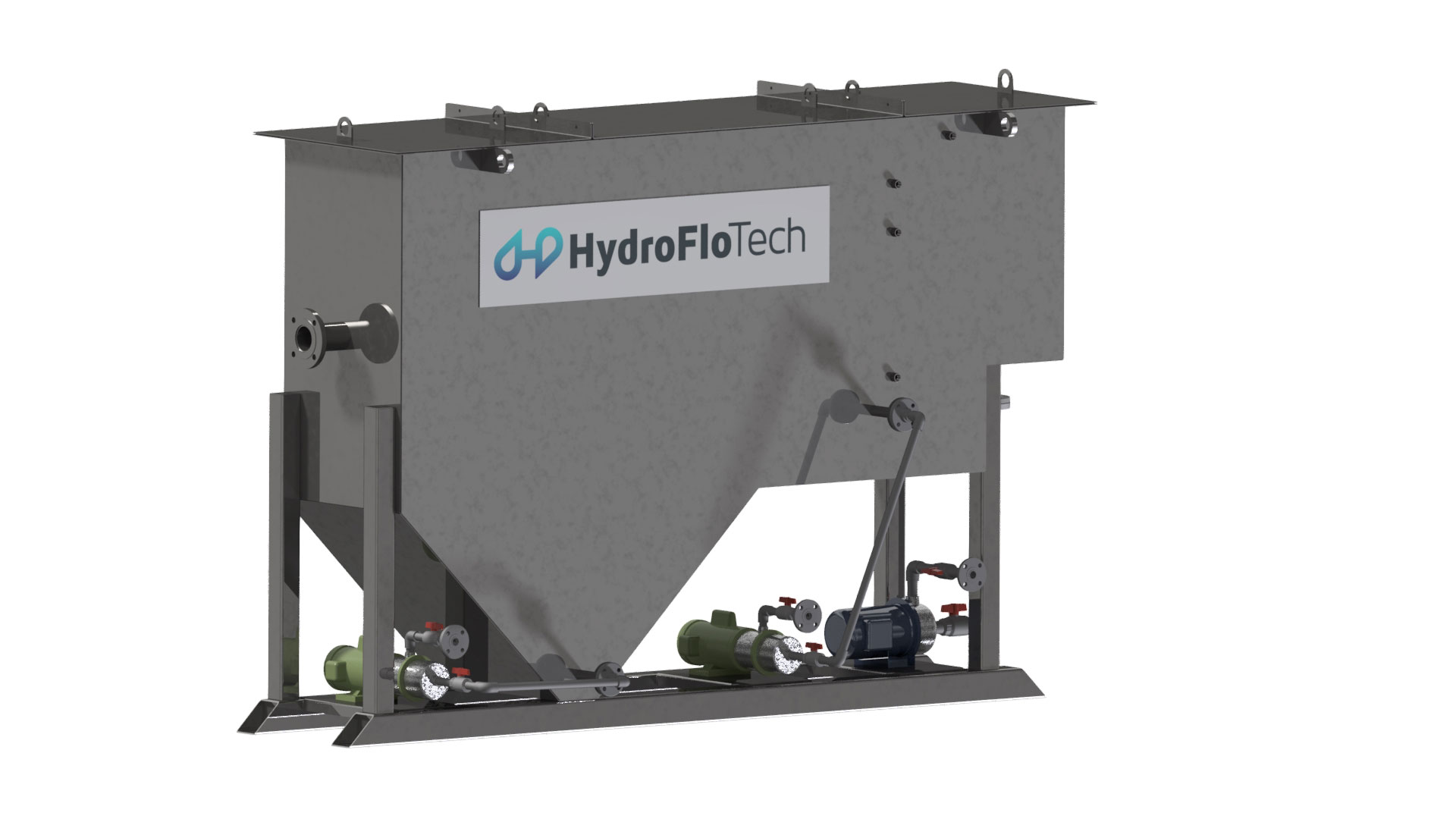
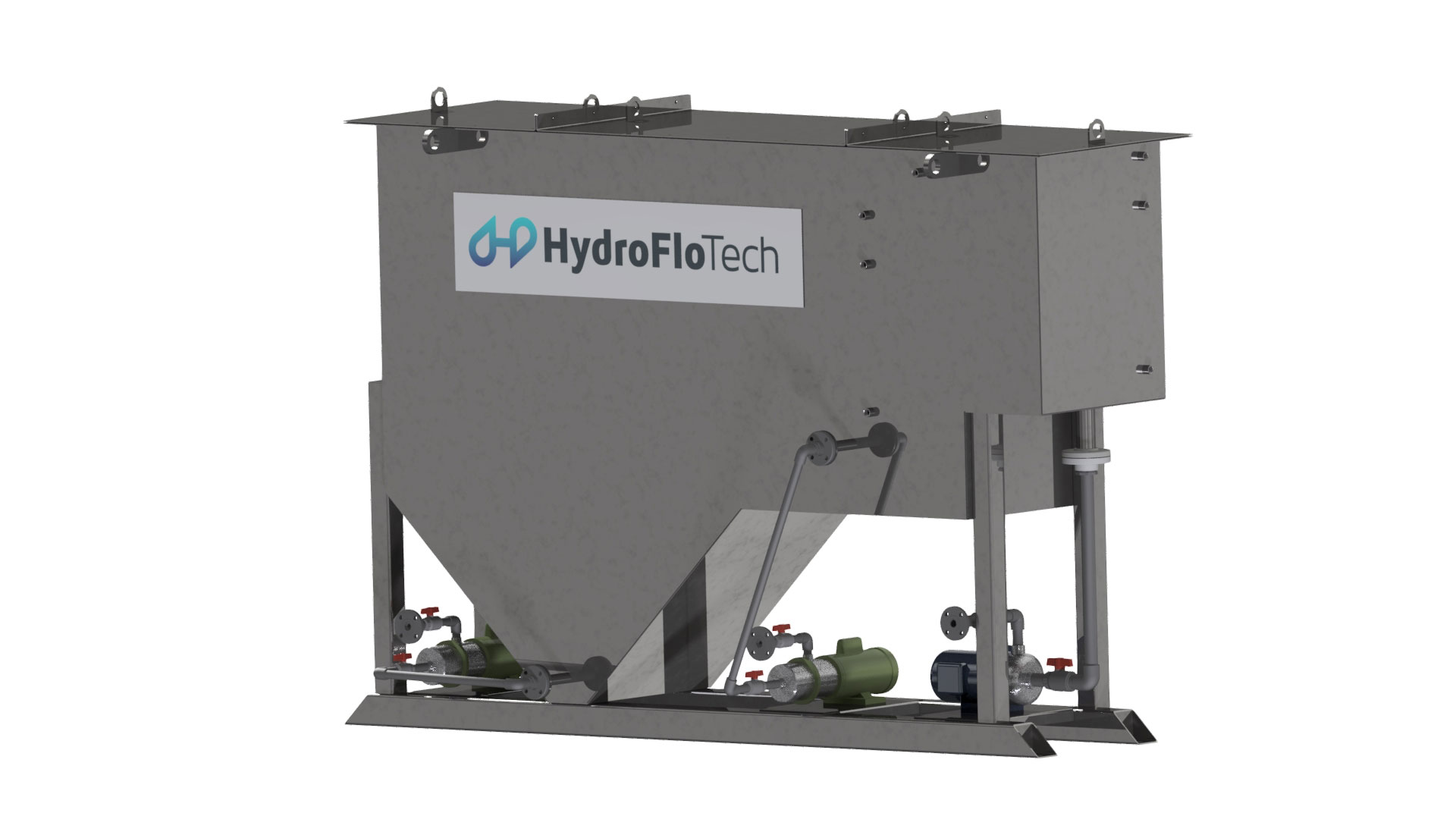
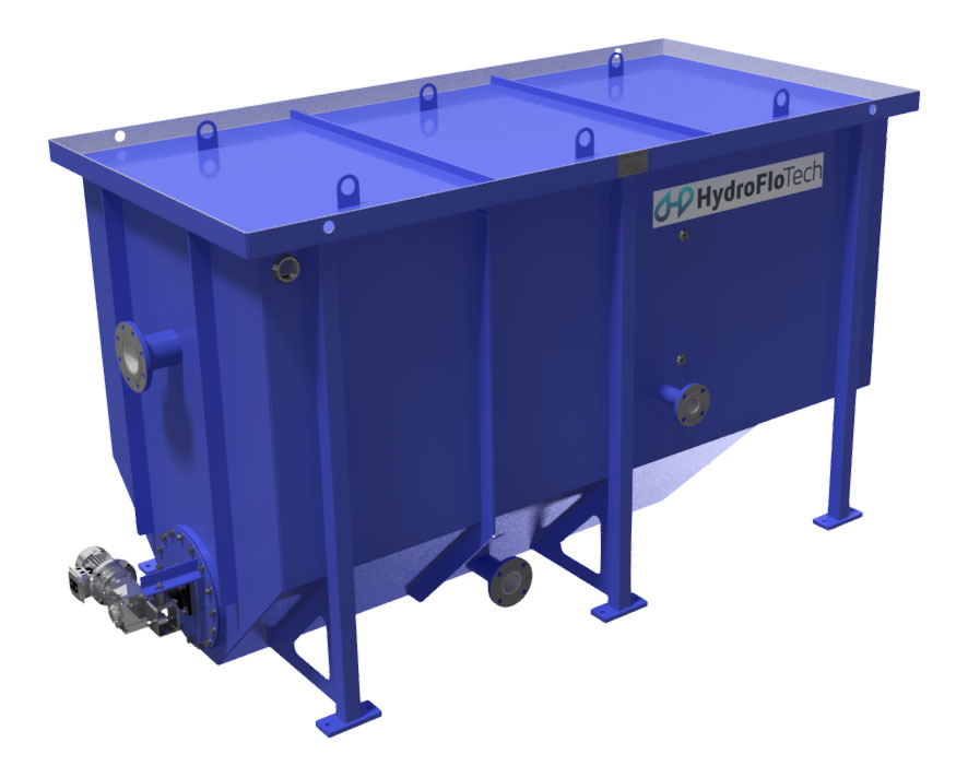
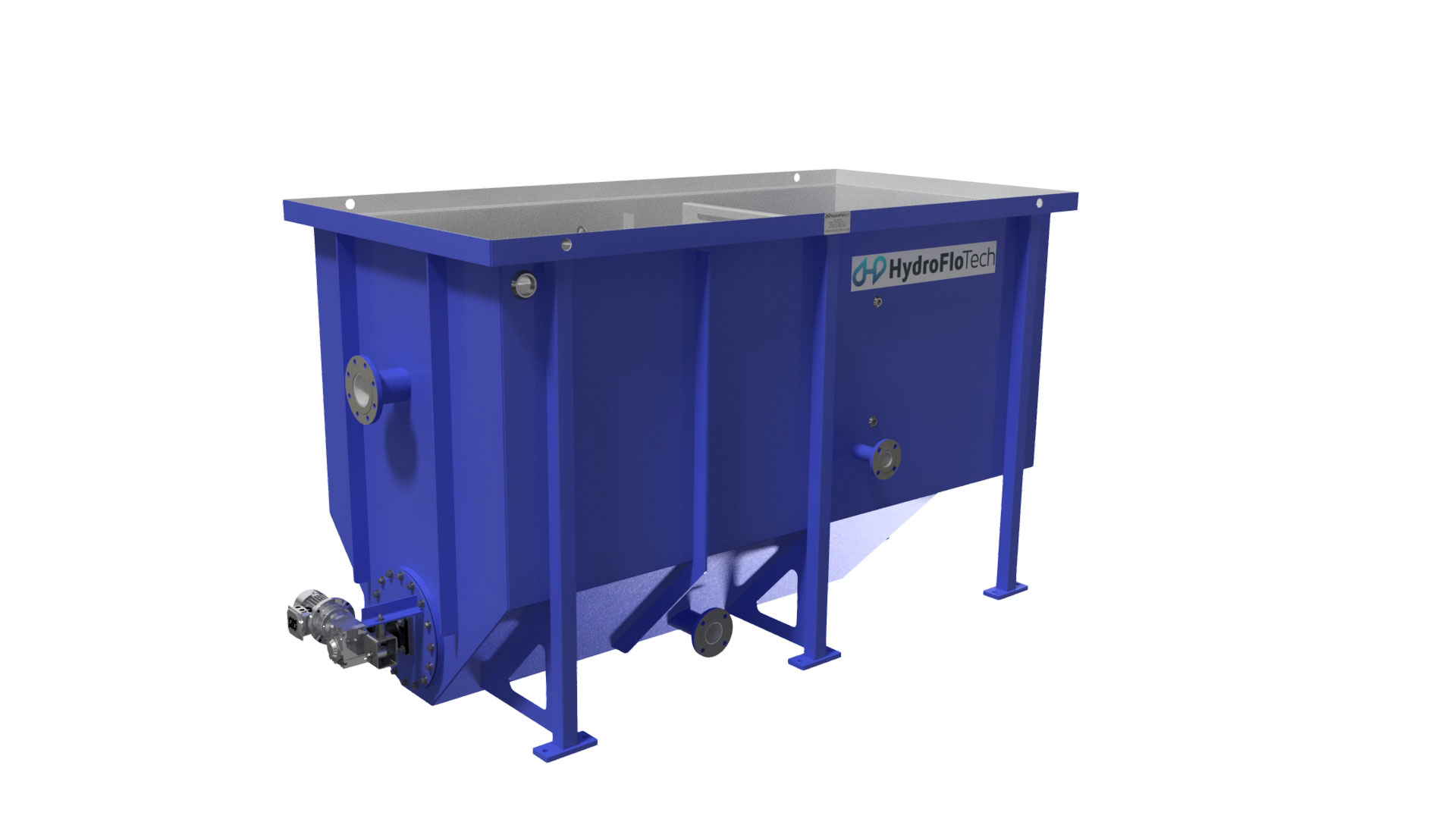
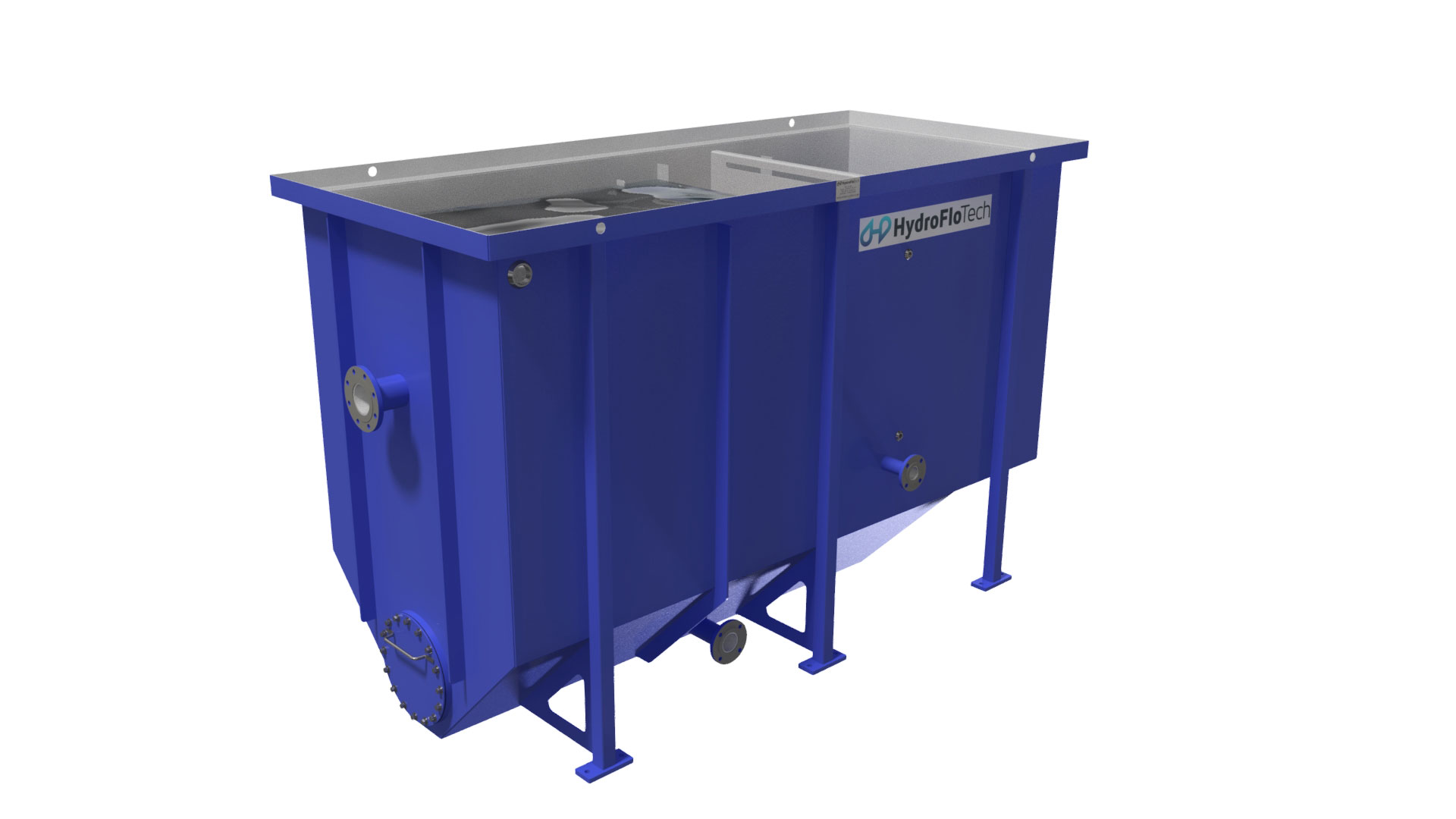
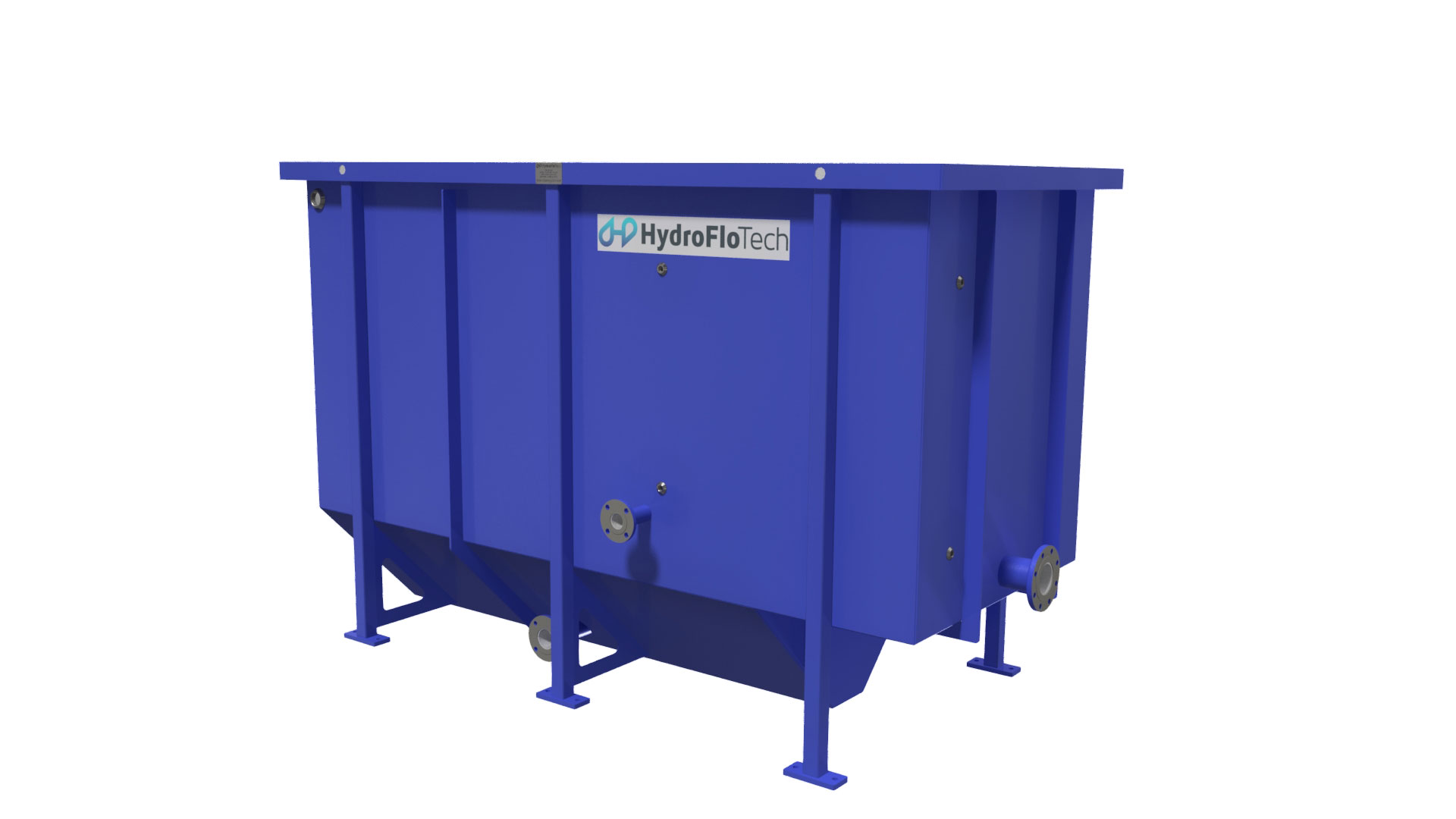
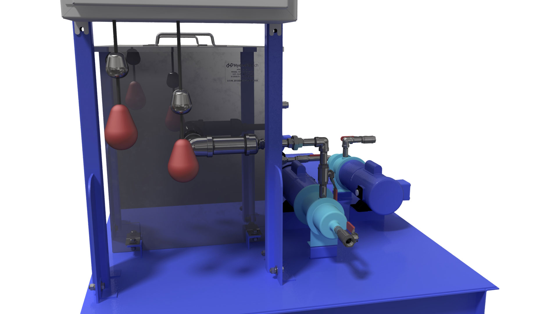
The separation cell is designed using elements of American Petroleum Institute’s publication 421 Feb. 1990 “Design of Oil-Water Separators” to ensure the best possible use of particle rise rate performance. The separation cell is a rectangular tank manufactured from carbon steel with an effluent surface baffle, 304 stainless steel full width adjustable overflow weir, effluent collection chamber with flanged outlet nozzle and recycle suction port, and angled float beaching plate. For our TotlSep “Hopper” TSH models also include a “V-Hopper” sludge collection chamber.
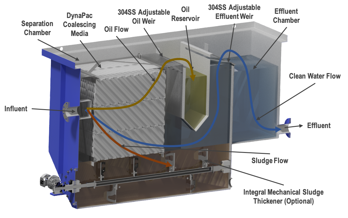
- Influent Diffusion Chamber
The flow shall enter the separator submerged, through an influent dispersion baffle. Dispersion across the depth and width of the Dynapac™ is to be achieved through the use of a non-clog diffuser. Heavy solids that fall out of suspension here shall be channeled to the sludge collection chamber (for TotlSep “Hopper” TSH models only). - Separation Chamber
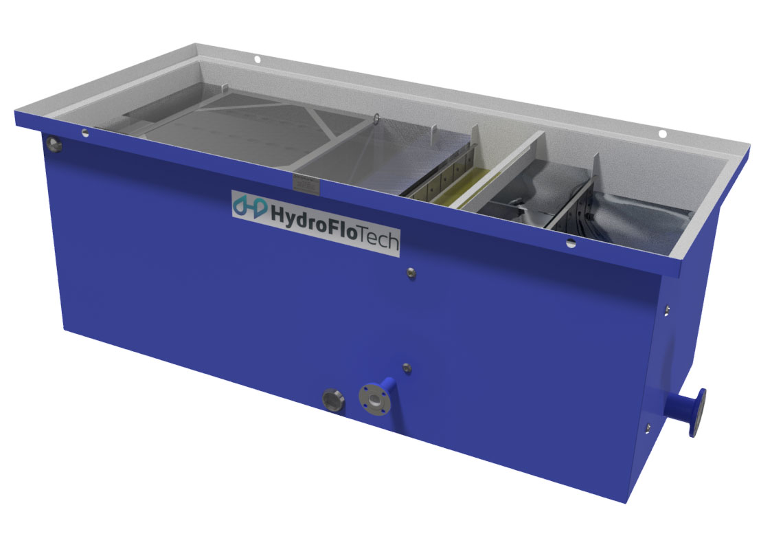
The Separation Chamber is designed to fit the exact amount of DynaPac™ cross corrugated coalescing media, sized for specific applications. Adequate space is to be left before and after the chamber to prevent short circuiting through the pack. DynaPacTM coalescing media is available in 0.5”, 0.75” and 1.25” sizes all in PVC, H-PVC, Polypropylene or 304 stainless steel. Depending on the correct sizing of the unit, this media (sized in cubic feet) provides the correct surface area (in square feet) for ideal separation. HydroFloTech oil water separator sizing sheets are a great resource to determine the size of media required by application (hyperlink). - Sludge Collection Chamber (for TotlSep “Hopper” TSH units)
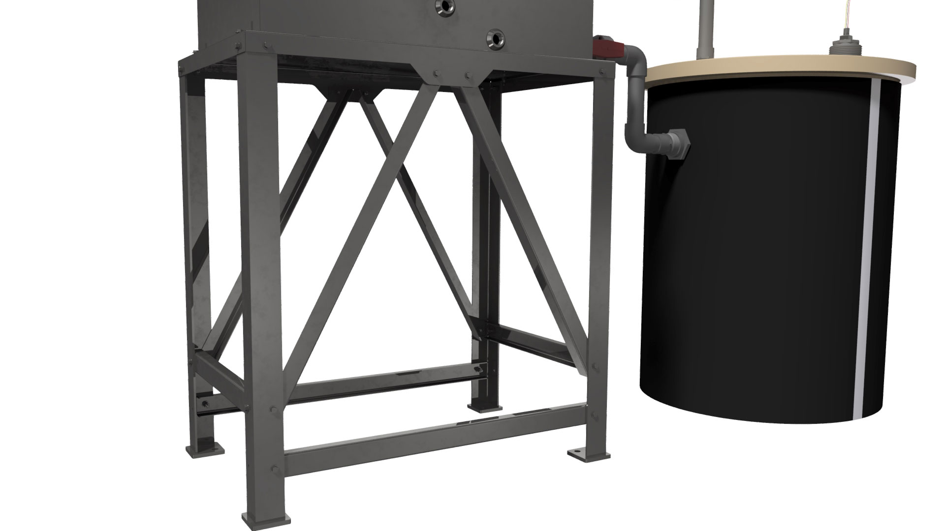
The sludge collection chamber shall be located directly beneath the coalescing media pack and provide ample storage capacity for the settled sludge. - Oil Reservoir
The oil discharge port is located adjacent to the separation chamber. As the oil floats and rises to the top of the DynaPacTM media pack in the separation chamber, the oil retention baffle in the oil reservoir captures this separated oil. - Effluent Chamber
The aqueous phase leaving the DynaPac™ shall pass under the oil reservior and up over the adjustable 304 stainless steel effluent weir, which shall maintain the liquid level throughout the separator. - Removable Lids
The entire separator can be covered with an optional bolt-down removable lid - Coalescing Media
The DynaPacTM coalescing media pack shall be fabricated of oleophilic cross corrugated coalescing media manufactured by HydroFloTech. Media is available in PVC, H-PVC, Polypropelene and 304 stainless steel.
| TotlSep™ Oil Water Separator – Model Specifications | |||||||||||||||
| TS MODEL # | MEDIA DIMENSIONS (Feet) | FLOW RATE (GPM) | CAPACITY (US Gallons) | FITTINGS (Inches) | ELEVATION (Inches) | UNIT DIMENSIONS (Inches) | Operating Weight (lbs.) | ||||||||
| CUBIC FEET OF MEDIA | (L x W x H) | Approx. (Min – Max) |
Oil Reservoir | Total Separator | Influent | Effluent | Influent | Effluent | Oil | L | W | H | |||
| TS-036 | 3 | 4 | 3 | 50 – 150 | 53 | 807 | 6 | 4 | 25 | 7 | 12 | 116 | 56 | 48 | 8,756 |
| TS-045 | 3 | 5 | 3 | 80 – 200 | 66 | 1,005 | 6 | 6 | 25 | 7 | 12 | 116 | 68 | 48 | 10,982 |
| TS-054 | 3 | 6 | 3 | 100 – 300 | 79 | 1,201 | 6 | 6 | 25 | 7 | 12 | 116 | 80 | 48 | 13,067 |
| TS-080 | 4 | 5 | 4 | 150 – 400 | 91 | 1,515 | 6 | 6 | 33 | 7 | 16 | 128 | 68 | 60 | 16,186 |
| TS-096 | 4 | 6 | 4 | 160 – 500 | 109 | 1,812 | 8 | 8 | 33 | 8 | 16 | 128 | 80 | 60 | 19,213 |
| TS-112 | 4 | 7 | 4 | 200 – 600 | 128 | 2,111 | 8 | 8 | 33 | 8 | 16 | 128 | 92 | 60 | 23,056 |
| TS-180 | 6 | 6 | 5 | 225 – 660 | 140 | 2,774 | 8 | 8 | 41 | 8 | 20 | 152 | 80 | 72 | 28,761 |
| TS-210 | 6 | 7 | 5 | 250 – 775 | 163 | 3,228 | 8 | 8 | 41 | 8 | 20 | 152 | 92 | 72 | 33,297 |
| TS-240 | 6 | 8 | 5 | 300 – 900 | 186 | 3,684 | 10 | 10 | 41 | 10 | 20 | 152 | 104 | 72 | 37,925 |
| TS-294 | 7 | 7 | 6 | 310 – 925 | 198 | 4,221 | 10 | 10 | 49 | 10 | 24 | 164 | 92 | 84 | 43,204 |
| TS-336 | 7 | 8 | 6 | 350 – 1,075 | 226 | 4,815 | 10 | 10 | 49 | 10 | 24 | 164 | 104 | 84 | 48,758 |
| TS-378 | 7 | 9 | 6 | 375 – 1,200 | 254 | 5,410 | 10 | 10 | 49 | 10 | 24 | 164 | 116 | 84 | 54,720 |
| TS-448 | 8 | 8 | 7 | 400 – 1,250 | 267 | 6,076 | 12 | 12 | 57 | 11 | 28 | 176 | 104 | 96 | 60,924 |
| TS-504 | 8 | 9 | 7 | 450 – 1,400 | 300 | 6,825 | 12 | 12 | 57 | 11 | 28 | 176 | 116 | 96 | 67,821 |
| TS-560 | 8 | 10 | 7 | 500 – 1,550 | 333 | 7,575 | 12 | 12 | 57 | 11 | 28 | 176 | 128 | 96 | 75,176 |
| TS-648 | 9 | 9 | 8 | 525 – 1,600 | 345 | 8,383 | 12 | 12 | 65 | 11 | 32 | 188 | 116 | 108 | 82,915 |
| TS-720 | 9 | 10 | 8 | 600 – 1,800 | 383 | 9,304 | 14 | 14 | 65 | 12 | 32 | 188 | 128 | 108 | 91,596 |
| TS-792 | 9 | 11 | 8 | 650 – 2,000 | 421 | 10,231 | 14 | 14 | 65 | 12 | 32 | 188 | 140 | 108 | 100,327 |
| TotlSep™ “Hopper” – Oil Water Separtor – Model Specifications | |||||||||||||||
| TSH MODEL # | MEDIA DIMENSIONS (Feet) | FLOW RATE (GPM) | CAPACITY (US Gallons) | FITTINGS (Inches) | ELEVATION (Inches) | UNIT DIMENSIONS (Inches) | Operating Weight (lbs.) | ||||||||
| CUBIC FEET OF MEDIA | (L x W x H) | Approx. (Min – Max) | Oil Reservoir | Sludge Hopper | Influent | Effluent | Influent | Effluent | Oil | L | W | H | |||
| TSH-036 | 3 | 4 | 1 | 50 – 150 | 53 | 199 | 6 | 4 | 25 | 25 | 32 | 116 | 56 | 68 | 10,466 |
| TSH-045 | 3 | 5 | 1 | 80 – 200 | 66 | 308 | 6 | 6 | 25 | 30 | 37 | 116 | 68 | 73 | 13,601 |
| TSH-054 | 3 | 6 | 2 | 100 – 300 | 79 | 442 | 6 | 6 | 25 | 35 | 42 | 116 | 80 | 78 | 16,853 |
| TSH-080 | 4 | 5 | 2 | 150 – 400 | 91 | 355 | 6 | 6 | 33 | 30 | 41 | 128 | 68 | 85 | 19,296 |
| TSH-096 | 4 | 6 | 2 | 160 – 500 | 109 | 509 | 8 | 8 | 33 | 36 | 46 | 128 | 80 | 90 | 23,658 |
| TSH-112 | 4 | 7 | 2 | 200 – 600 | 128 | 690 | 8 | 8 | 33 | 41 | 51 | 128 | 92 | 95 | 29,011 |
| TSH-180 | 6 | 6 | 3 | 225 – 660 | 140 | 643 | 8 | 8 | 41 | 36 | 50 | 152 | 80 | 102 | 34,323 |
| TSH-210 | 6 | 7 | 3 | 250 – 775 | 163 | 872 | 8 | 8 | 41 | 41 | 55 | 152 | 92 | 107 | 40,819 |
| TSH-240 | 6 | 8 | 4 | 300 – 900 | 186 | 1,136 | 10 | 10 | 41 | 47 | 60 | 152 | 104 | 112 | 47,699 |
| TSH-294 | 7 | 7 | 4 | 310 – 925 | 198 | 963 | 10 | 10 | 49 | 42 | 59 | 164 | 92 | 119 | 51,635 |
| TSH-336 | 7 | 8 | 4 | 350 – 1,075 | 226 | 1,255 | 10 | 10 | 49 | 47 | 64 | 164 | 104 | 124 | 59,624 |
| TSH-378 | 7 | 9 | 4 | 375 – 1,200 | 254 | 1,584 | 10 | 10 | 49 | 52 | 69 | 164 | 116 | 129 | 68,330 |
| TSH-448 | 8 | 8 | 6 | 400 – 1,250 | 267 | 1,373 | 12 | 12 | 57 | 48 | 68 | 176 | 104 | 136 | 72,875 |
| TSH-504 | 8 | 9 | 6 | 450 – 1,400 | 300 | 1,734 | 12 | 12 | 57 | 53 | 73 | 176 | 116 | 141 | 82,883 |
| TSH-560 | 8 | 10 | 8 | 500 – 1,550 | 333 | 2,137 | 12 | 12 | 57 | 58 | 78 | 176 | 128 | 146 | 93,749 |
| TSH-648 | 9 | 9 | 8 | 525 – 1,600 | 345 | 1,884 | 12 | 12 | 65 | 53 | 77 | 188 | 116 | 153 | 99,627 |
| TSH-720 | 9 | 10 | 8 | 600 – 1,800 | 383 | 2,322 | 14 | 14 | 65 | 59 | 82 | 188 | 128 | 158 | 112,461 |
| TSH-792 | 9 | 11 | 8 | 650 – 2,000 | 421 | 2,805 | 14 | 14 | 65 | 64 | 87 | 188 | 140 | 163 | 125,721 |
| Equipment Designing Data & Sizing Sheet Calculations | Drawings | Specifications | Installation, Operation & Maintenance Manual |
|---|---|---|---|
| Oil/Water Separator Theory of Operation | TotlSep General Arrangement Drawing | TotlSep Engineering Specification | TotlSep Standard IO&M |
| Oil/Water Separator Design Parameters | TotlSep “Hopper” General Arrangement Drawing | “Common” Engineering Specification | TotlSep Hopper Standard IO&M |
| TotlSep Sizing Spreadsheet | General IO&M Considerations Applicable to all HydroFlo Manufactured Equipment |