Winery

The winery industry involves processing various wines and related production materials. Wastewater produced in winemaking facilities contains mainly dissolved sugars and alcohol compounds like ethanol, associated with the wine.
Most of the wastewater generated in wineries is associated with winemaking happens during seasons cleaning activities. Typical wastewater is high in chemical oxygen demand (COD), biological oxygen demand (BOD) along with a low pH. The concentration of ethanol is high when vats are emptied and washed out, but low when crushing equipment is cleaned. The converse applies for sugars The volume and chemical composition (inorganic and organic) of the wastewater are highly variable and depend on a variety of factors:
- Cleaning / sanitizing products used: Inorganic contaminants in wastewater come from use of sodium-based cleaning and sanitizing products are used in most wineries.
- Influent water characteristics
- Winery production processes: Organic contaminants in wastewater come from various winery production processes including crushing, fermentation, maturation / stabilization, decanting and bottling.
- Grape Variety: White grapes (typically late harvest) have high sugar while red grapes (early harvest) are low sugar
Design Considerations
The Dissolved Sugars in the wastewater (BOD / COD) cannot simply be separated by mechanical means. These dissolved sugars need to be “undissolved” and then removed. The primary mechanism used to remove these sugars is the introduction of certain specific bacteria in the wastewater, which feed on specific organic dissolved sugars. The bacterial cultures are maintained by supplying nutrients to the bacteria and abundant oxygen.
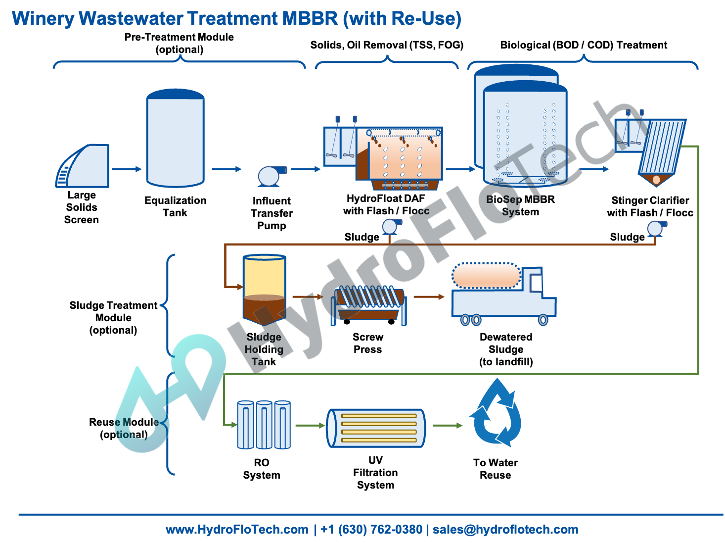
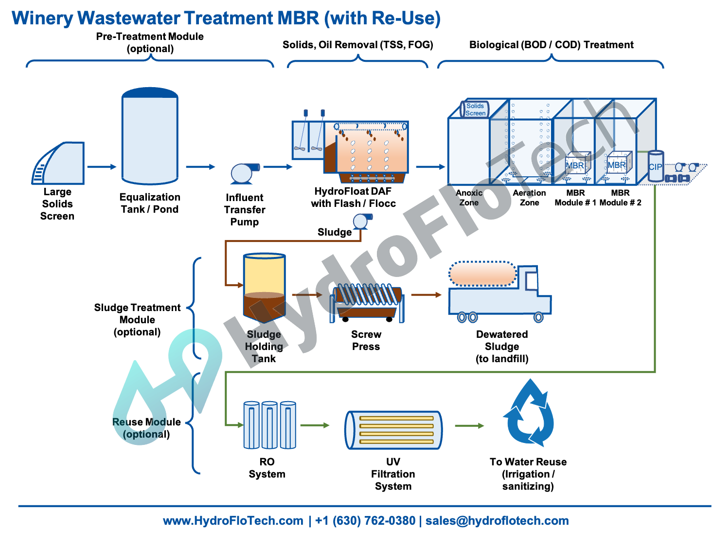
HydroFloTech has designed a fully modular system for winery facilities. This system can be designed to be a mobile (trailer based) or container-based system:
Pre-Treatment Module: This module removes large solids and equalizes the water prior to any further treatment. The goal of this module to get the water provide the downstream treatment equipment with an equalized stream of water which if free from large solids.
Side Hill Screen / Grit Removal System: “Side hill” or “Grit Removal Systems” are used for the removal of large insoluble material from wastewater flows. These screens or systems are used on process and wastewater streams for particles that need to be removed to protect downstream systems. These screens can also be used for product recovery; large solids separation and mixed settleable solids for both municipal and industrial applications.
The HydroFloTech Side Hill Screen or Grit Removal System maximize solids removal in an easy to maintain unit. The screen is a barrier by which material larger than the gap or slot size may not pass, allowing the water to continue through.
Equalization Tank: HydroFloTech can work with an existing equalization “EQ” tank or provide one. Materials of construction can includes: Fiberglass (FRP), HDPE, steel (carbon steel or stainless steel), concrete, or even in-ground storage pits / ponds. The purpose of the equalization tank is to “equalize” and narrow any variances in water characteristics. The EQ tank also acts as a great buffer for two main purposes: First the EQ tank provides a buffer storage capacity in situations when there is a temporary surge in flowrate. This allows the system to be smaller than the peak surge flowrate. Secondly, the EQ tank also provides the ability to “narrow” any spikes in any contaminants.
Chemical Pre-Treatment and Solids / Fats & Oils Removal: This module chemically treats the water with pH adjustment (as necessary), coagulant and polymers to enhance the ability of HydroFloTech inclined plate clarifiers or dissolved air floatation systems (DAF) to effectively remove any Total Suspended Solids (TSS) or Fats, Oils and Grease (FOG).
ChemiSep Chemical Pre-Treatment System: The efficacy of any wastewater is as good as the pre-treatment of the wastewater prior to removal of any impurities. The HydroFloTech ChemiSep Pre-Treatment System provides great flexibility in treating various wastewater profiles:
- Stage 1 – pH Adjustment / Precipitation & Coagulation: pH is raised (or lowered) with the pH controller using caustic (or acid). A coagulant is added to cause precipitation of the solids. A “pin floc” is developed indicating that the suspended solids are precipitated.x
- Stage 2 – Flash Mix: The wastewater with it’s precipitated pin floc is introduced to the flash mix zone where a polymer flocculent is added. This stage maximizes flocculent dispersion throughout the coagulated wastewater.
- Stage 3 – Flocculation: The wastewater is now introduced to the slow mix zone to agglomerate the floc into larger particles suitable to be enmeshed with the air bubbles.
HydroFloat Dissolved Air Flotation (DAF) System:
The flocculated wastewater is introduced into the HydroFloat DAF inlet where the floc particles are comingled with a pressurized dissolved fine bubble recycle stream. The floc particles attach to the bubbles and float to the surface where they are mechanically skimmed into the float scum sludge chamber. The treated water then exits the end of the DAF and flows downstream to sewer or further treatment if necessary. The DAF system bubbles come from a Recycle Air Dissolving system that takes a portion of treated effluent, pressurizes it and introduces air to be dissolved. The dissolved air comes out of solution and forms a fine bubble stream when the pressure is released at the DAF entrance in the presence of floc wastewater.
BOD / COD Removal: This module removes Biological Oxygen Demand (BOD) and Chemical Oxygen Demand (COD) from the wastewater primarily through two different options:
Option 1: BioSep MBBR System: The BioSep MBBR system comes in handy if the water has high levels of BOD / COD (upwards of 500+ mg / l).
Basin: The MBBR process takes place in a basin/tank, also known as a bio-reactor or as an aeration tank. The size of this bio-reactor depends on the filtration needs of a particular plant. Influent enters this bio-reactor for treatment. MBBR aeration tanks are open at the top or vented adequately, exposing the water to the open air, which makes this an aerobic process of filtration.
Media: The basin is full of thousands of small plastic chips, called media or carriers. These media may occupy as much as 40 to 65% of the tank. Their design maximizes the surface area they provide for biofilm to grow on them. Many carriers resemble wheel-shaped, pucks They mirror the density of water, allowing them to mix throughout the fluid, rather than floating or sinking.
Aeration grid: Another thing that helps the media move effectively throughout the tank is an aeration grid. This device is essentially like a fan located at the bottom of the reactor tank. The aeration grid helps keep carriers in motion so they can come into contact with all the waste present and efficiently decompose it, and introduces more oxygen into the tank.
Sieve: The mesh material allows water to pass through, but keeps the plastic carriers inside the bio-reactor.
Clarifier: The bio-sludge generated through the BioSep MBBR System is removed by using a clarification system.
ChemiSep Pre-Treatment System: Water is run through two individual stages of tanks for separating the bio-sludge from the water.
Clarifier: The flocculated wastewater is introduced into the clarifier where the settling particles accumulate in the sludge chamber. The clarified water then exits the clarifier and flows downstream to sewer or further treatment if necessary.
Option 2: BioSep MBR System: The BioSep MBR System is very helpful if the water needs to be recycled / re-used or has lower levels of BOD / COD.
The system has the following components:
- Primary / Fine Screen: A screens that removes trash from the waste stream is required preceding the equalization basin.
- Equalization Basin – An EQ basin with aeration diffusers and blower.
- Pump Skid: A pump skid containing equalization transfer pumps, WAS pumps, and EQ/WAS blowers. EQ transfer pumps will convey wastewater from the EQ basin into the secondary fine screen on the MBR process tank. The blowers will feed aeration equipment in the EQ and sludge holding tanks. WAS pumps pull WAS from the MBR process tank to the sludge holding tank. 10% of the WAS is recycled back to the screens.
- Modular MBR: The Modular MBR System is configured with one Anoxic (AX) Zone, one Pre-Aeration (PA) Zone, and Membrane (MB) Zones. Each zone is separated by a welded baffle structurally designed such that any zone can be fully drained if needed.
- Clean in place (CIP) Tank / Wash Water System: Clean-in-place system is required for regular membrane maintenance. Automatic CIP eliminates the need for the tank and dose pump but requires a plant water supply and additional chemical feed equipment. Wash water is also required for both primary/fine screens.
- Chemical Feed System: Chemical feed systems are included for the addition of alkalinity, carbon, and alum for phosphorus removal.
- Sludge Holding Tank: A sludge holding tank holds the undissolved BOD / COD which is separated from the process water a sludge.
Sludge Management Module: This module removes the precipitated solids from the water and converts those solids into dewatered “sludge” which may be eligible for re-use or landfill disposal.
Sludge Tank with Sludge Transfer Pump: The accumulated sludge is periodically removed from the clarifier and sent to a sludge holding tank where it further thickens for disposal or dewatering.
Sludge Dewatering: Sludge dewatering is typically handled by a HydroPress Filter Press or Screw Press. After processing a batch of “sludge” the filter press or screw press is emptied of “chrome cake” which is a semi solid of approximately 20-35 % solids. Chrome cake is high in chrome and sulfite and should be disposed of according to environmental regulations.
Re-Use Module: This module further reduces any remaining solids and biological / bacterial growth in the water to make it suitable for re-cycling or re-use.
RO System: The RO System removed any remaining dissolved solid (TDS) in the wastewater. The effluent coming out of the RO System is suitable for re-cycling / re-use.
UV Filter System: The UV Filter System finishing a final sanitizing of the water. The UV Filter System allows for the treated water to be used for most re-use / recycling purposes.