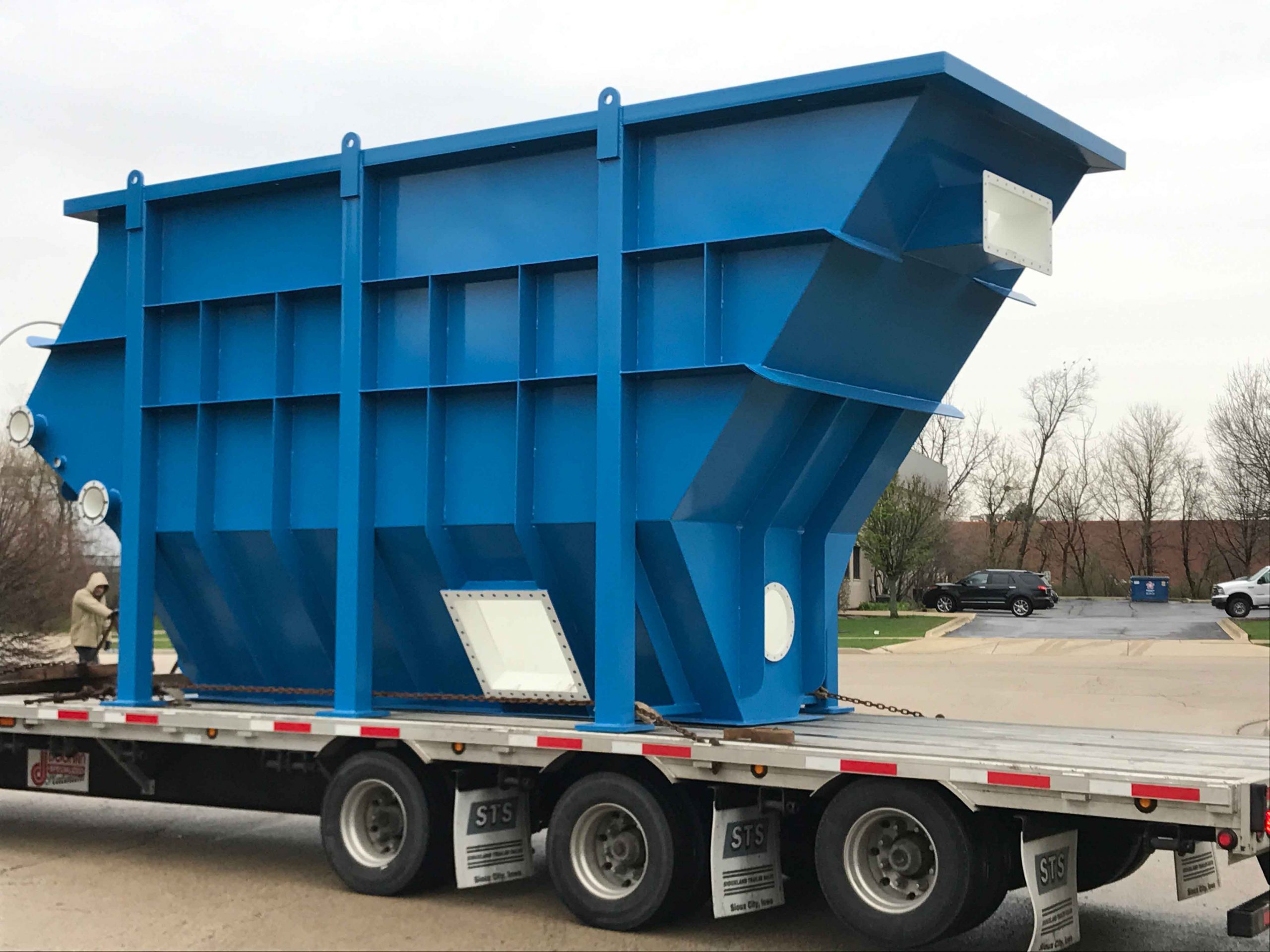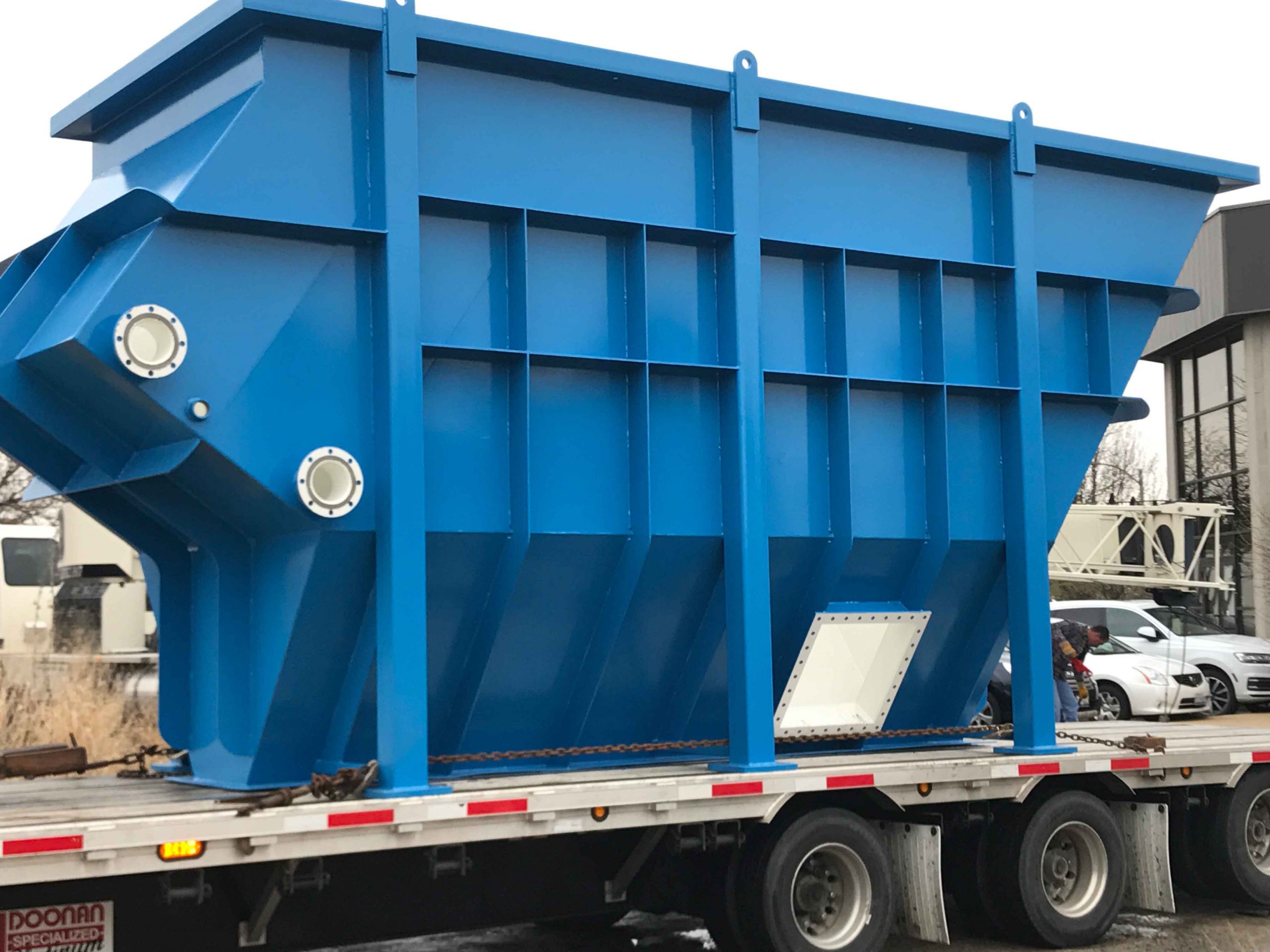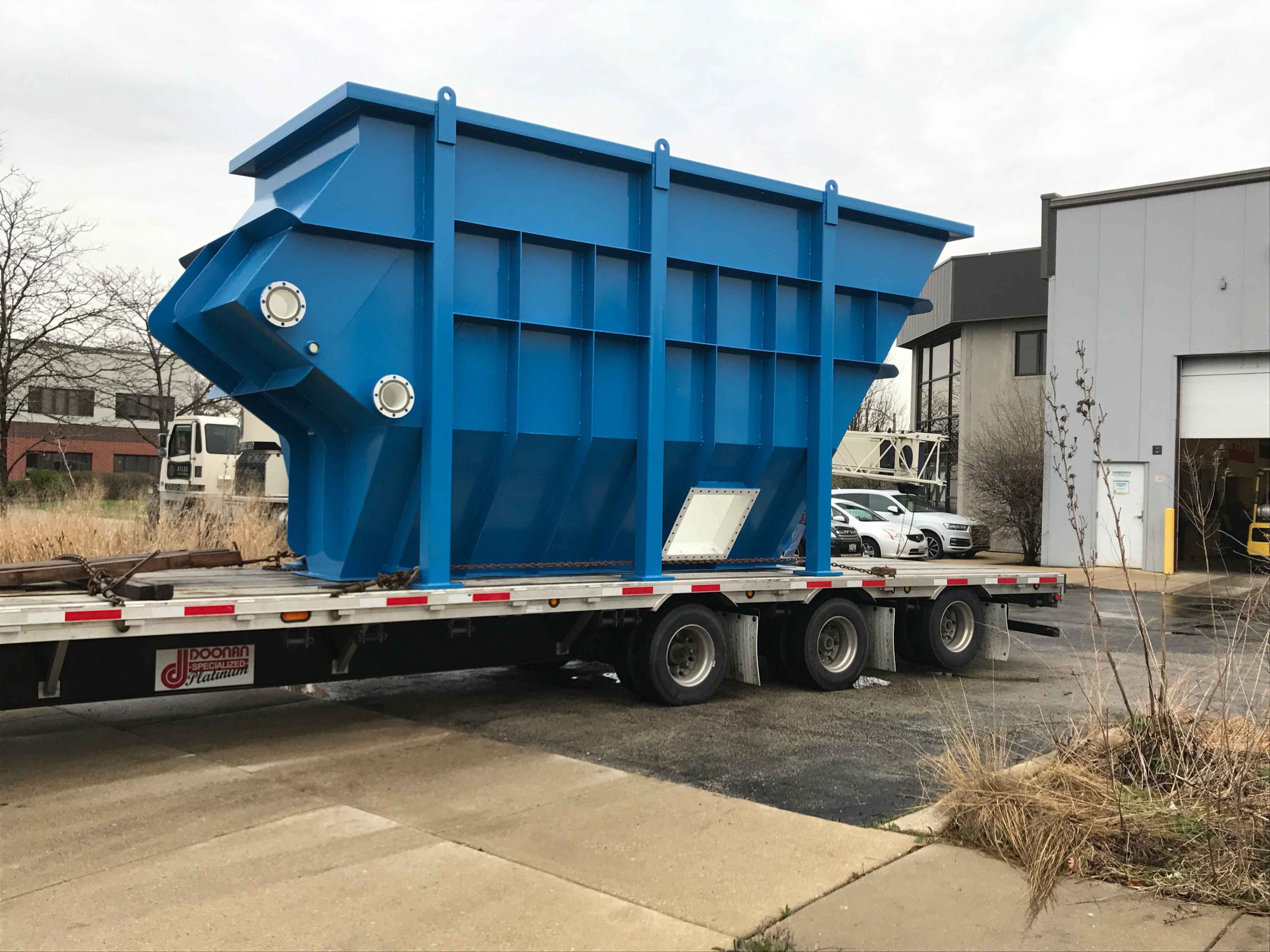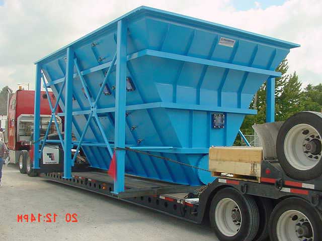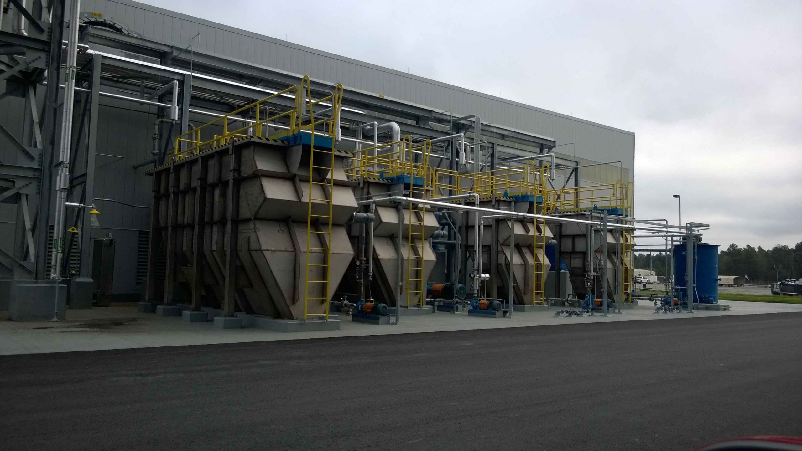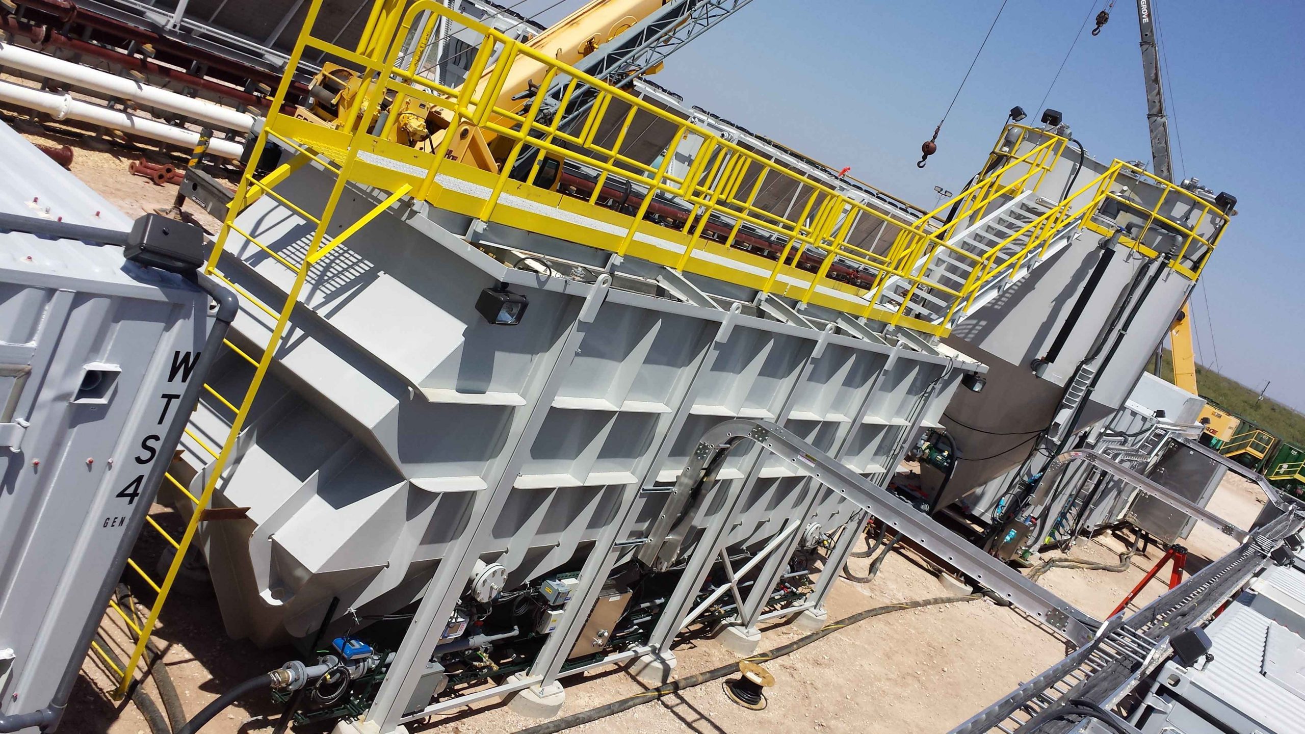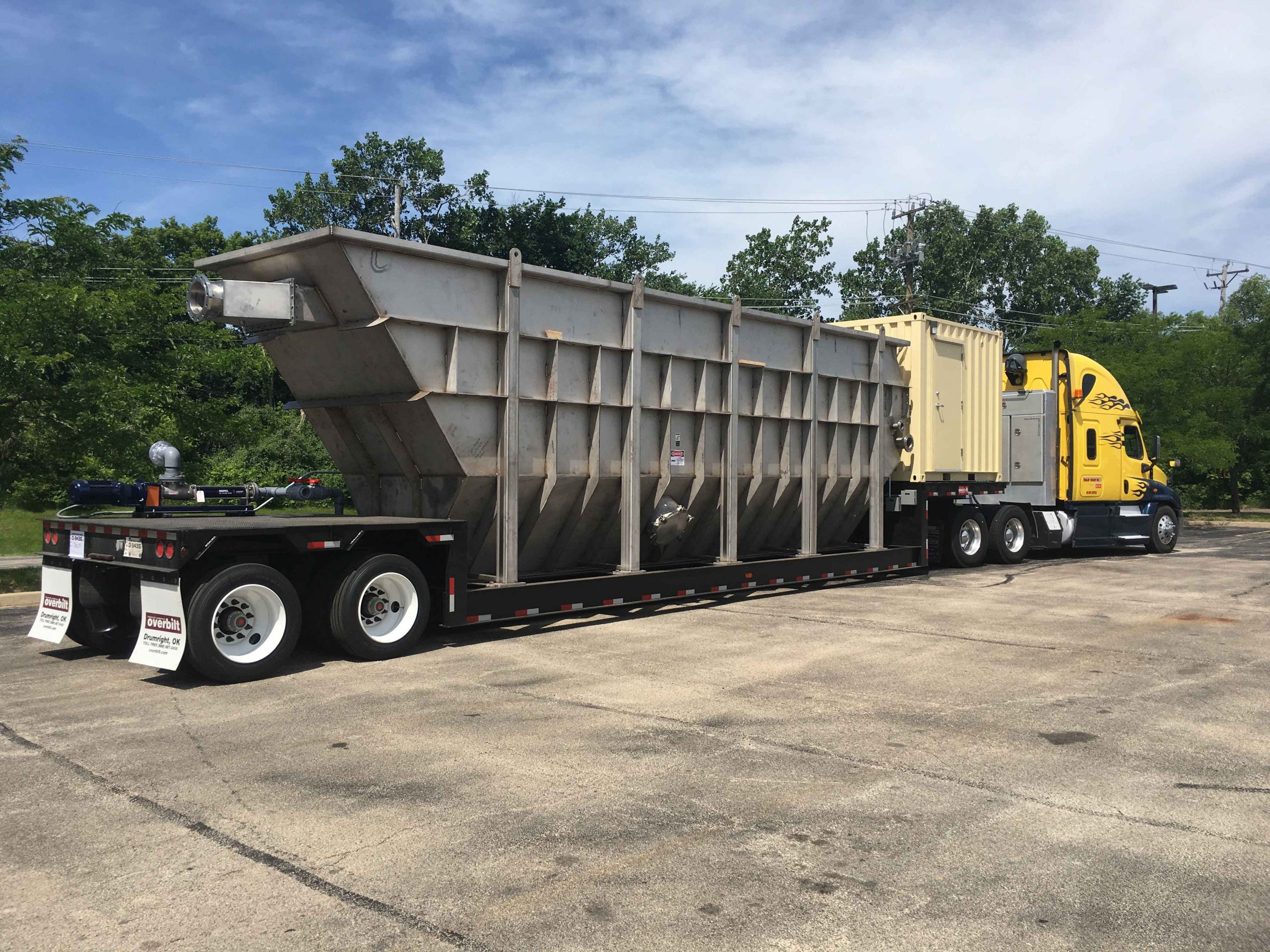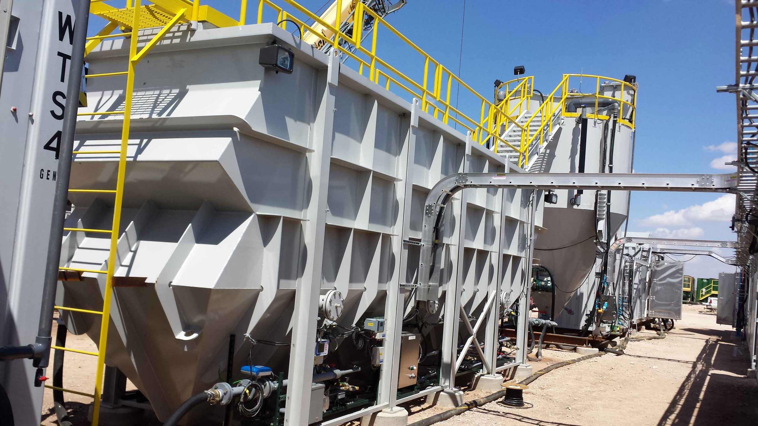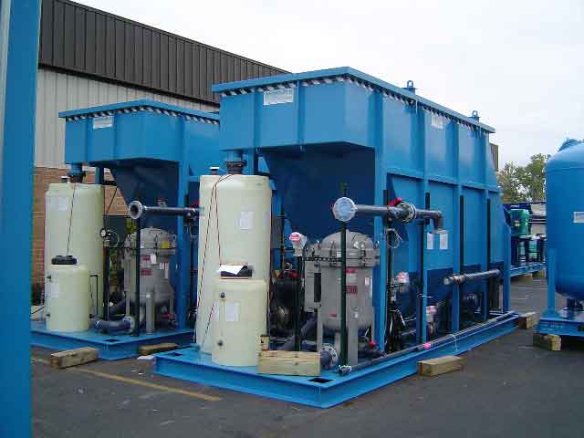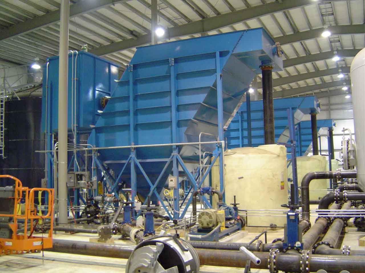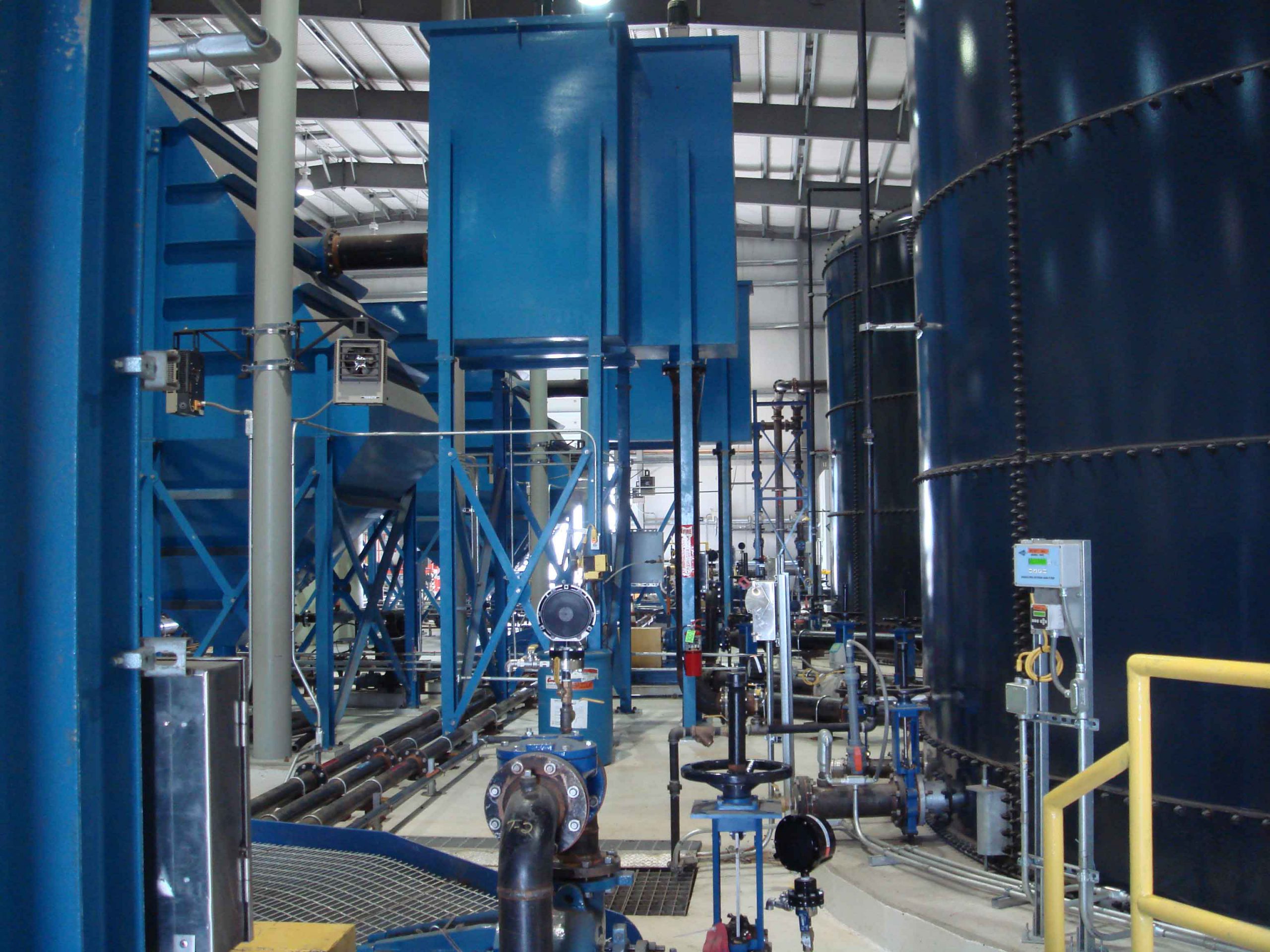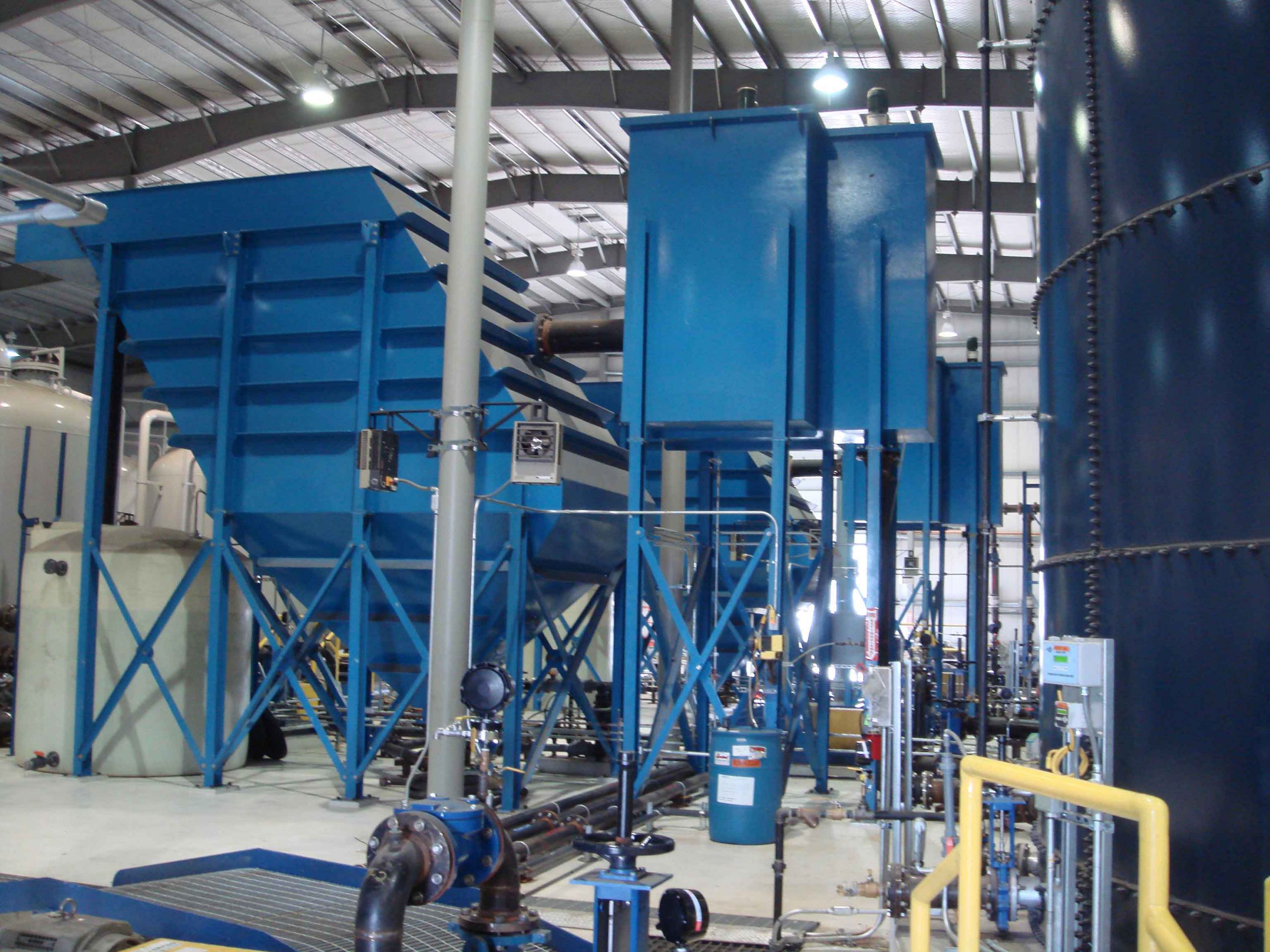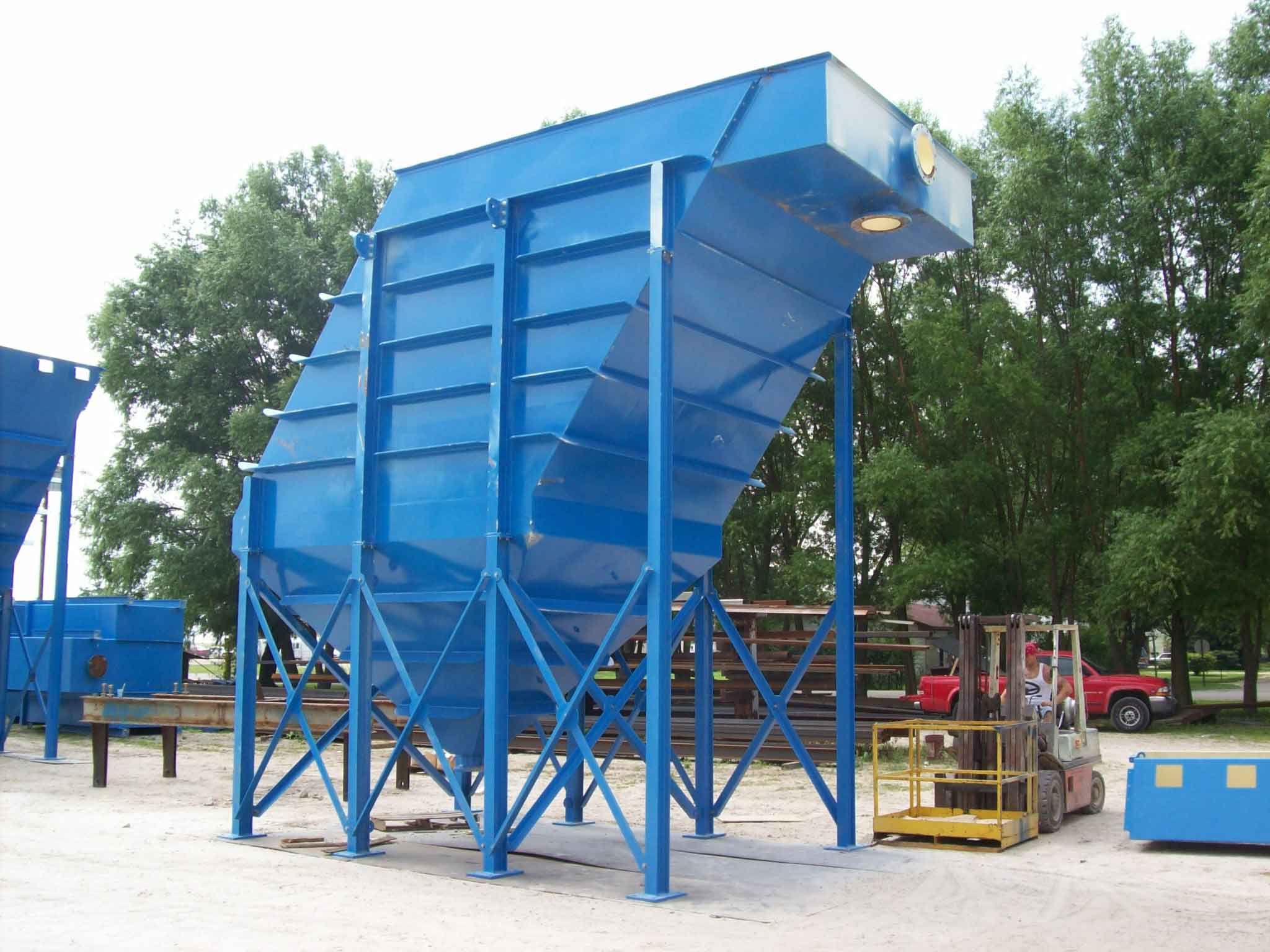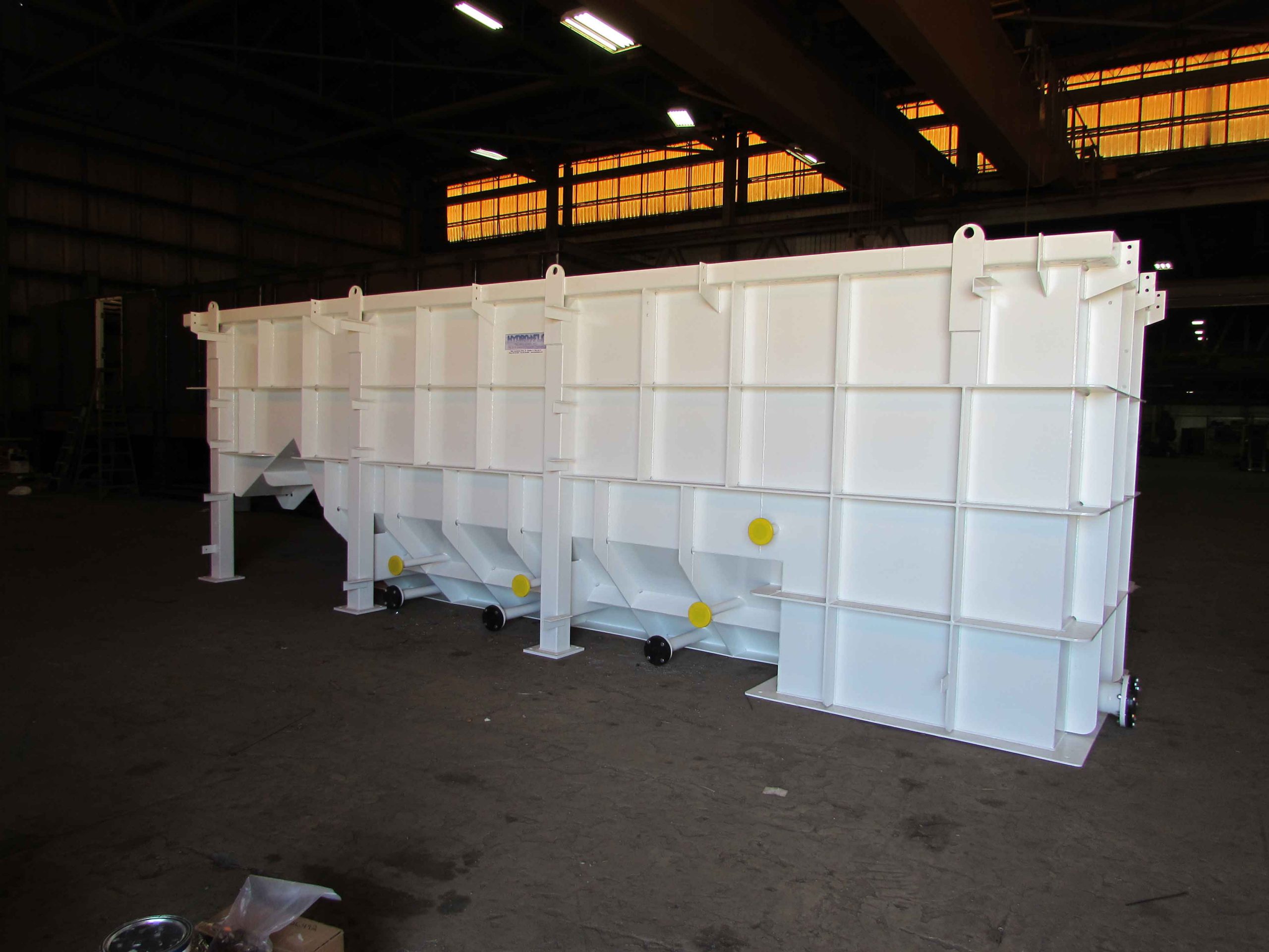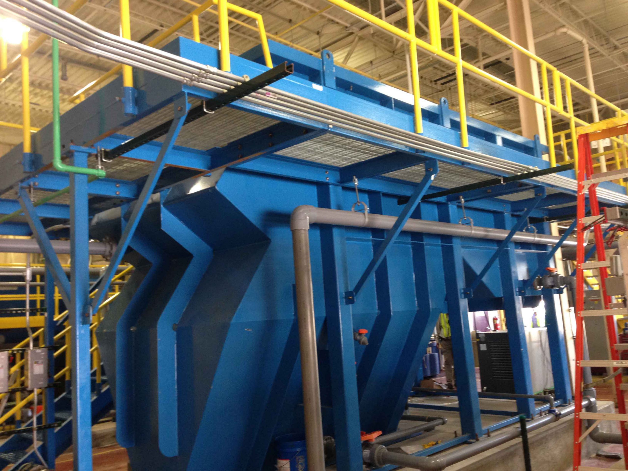

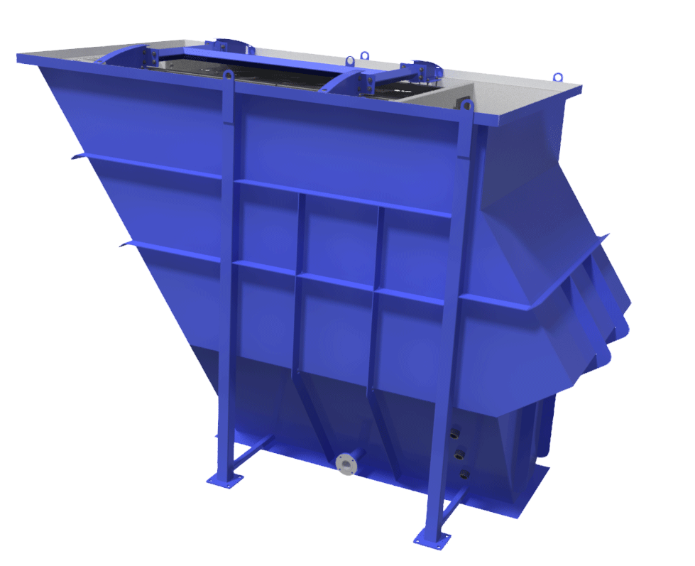
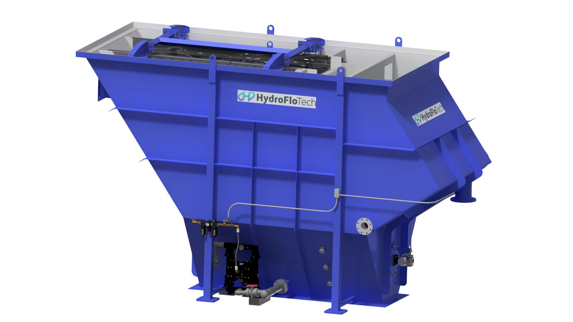
ClariMax
Standard Features
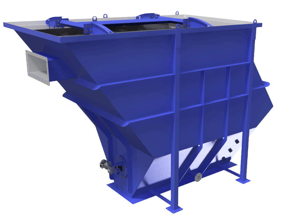
- Proprietary co-current and counter-current flow design for smaller footprint and better efficiency
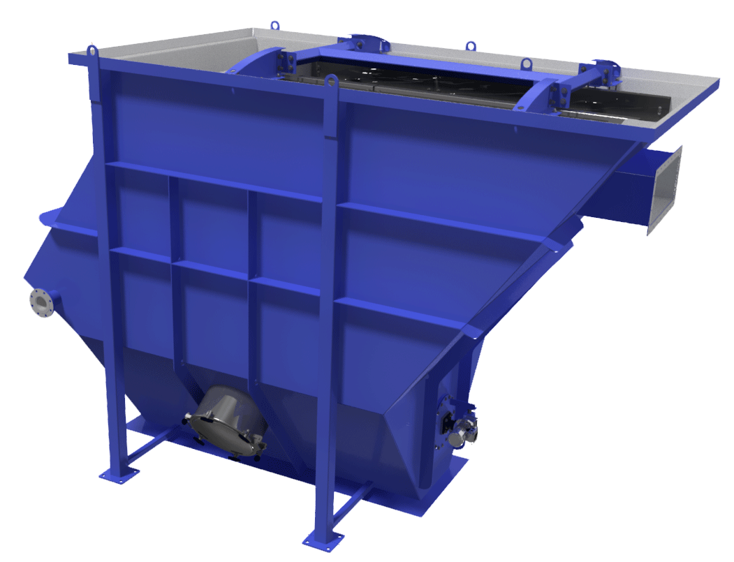
- Adjustable effluent V-notch troughs
- Epoxy coated ASTM A-36 carbon steel tank
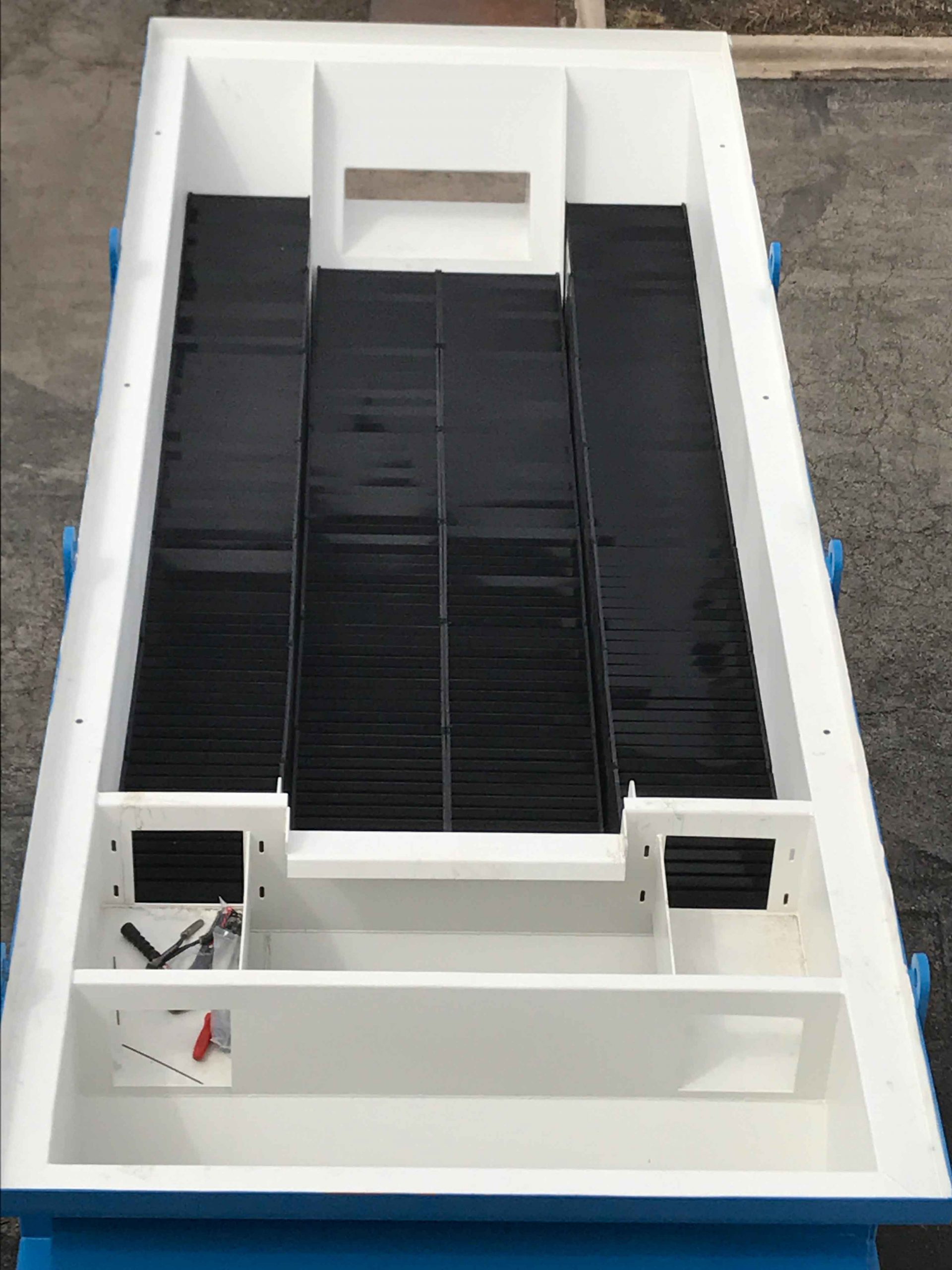
- Polypropylene plate packs
- Integral mechanical sludge thickener
- Standard units can be manufactured for flows up to 2,000 gpm and above
- Seamlessly integrates with other HydroFloTech wastewater products
Available Options
The most turbulent area found in “standard” inclined plate clarifier design is the area between the influent trough and the entrance to the plate pack. Short circuiting, high velocity areas and Eddy currents are present throughout this area, creating turbulence and misdistribution at the main plate pack entry areas.
In researching ways to minimize these problems, we discovered something interesting. First we altered the influent configurations and influent baffling. These changes did help minimize these issues but not enough to make a significant difference. Our real breakthrough came when we combined co-current and counter-current designs. This “hybrid” design greatly improved fluid dynamics throughout the entire clarifier. This configuration also allows us to take advantage of both co-current and counter-current design principles (as detailed in “Wastewater Engineering” by Metcalf and Eddy). The results are a step up from any of the other clarifier designs available today.
The net benefit of this “hybrid” design is greatly improved hydraulic loading and an improvement in the overall efficiency of the clarifier.
Influent distribution is greatly improved.
HydroFloTech’s influent configuration allows for the largest influent trough configuration available in the market. This huge 504 square inch connection between the clarifier and the flash/floc tank reduces influent velocities to the lowest available anywhere. This creates the ideal transition from clarifier influent to the primary co-current plate packs. The cross-sectional resistance created by the primary co-current plate packs in combination with the counter-current plate packs and HydroFloTech’s adjustable effluent trough system gives us better influent flow distribution than any other style clarifier on the market. This gives us far superior plate coverage and greater operation efficiencies than traditional designs.
Large quantities of solids are immediately removed from the waste stream by the co-current section.
The largest, heaviest, fastest settling floc particles are all trapped by the central co-current pack. Over 40% of the TSS are removed in this section. Often, numbers in excess of 50% are attainable. These solids are carried along the surfaces of the co-current plate packs (past the flow transition point from co-current to counter-current) directly into the sludge collection chamber.
Solids handling, as well as solids loading ratios are greatly improved over the typical counter-current designs available in the market.
One of the greatest issues faced by traditional counter-current clarifiers is the impact that accumulated solids have on overall clarifier efficiency. As the solids accumulate on the surfaces of the plates, they have to migrate along the surfaces of the plate to the bottom of the plate where they are discharged into the sludge collection chamber. As these solids accumulate, they reduce the effective “gap” or space between the plates. This increases the velocities through the plate packs reducing the clarifiers efficiency and increasing the possibility of floc carryover. By eliminating large quantities of solids in the co-current pack section, we are reducing the solids loading on the counter-current section. Less solids in the counter-current section means that our plate gaps will remain larger than other clarifier designs. Larger gaps mean lower overall velocities and less probability of floc carryover.
By utilizing the influent distribution area, our overall package is more compact than any competitive model.
Space is always a major consideration in the design, as well as the overall cost, of any water treatment facility. HydroFloTech’s hybrid design reduces a typical clarifier’s footprint by as much as 25%.
These advanced design elements, along with our standard features, make the HydroFloTech ClariMax™ the finest Inclined Plate Clarifier available today.
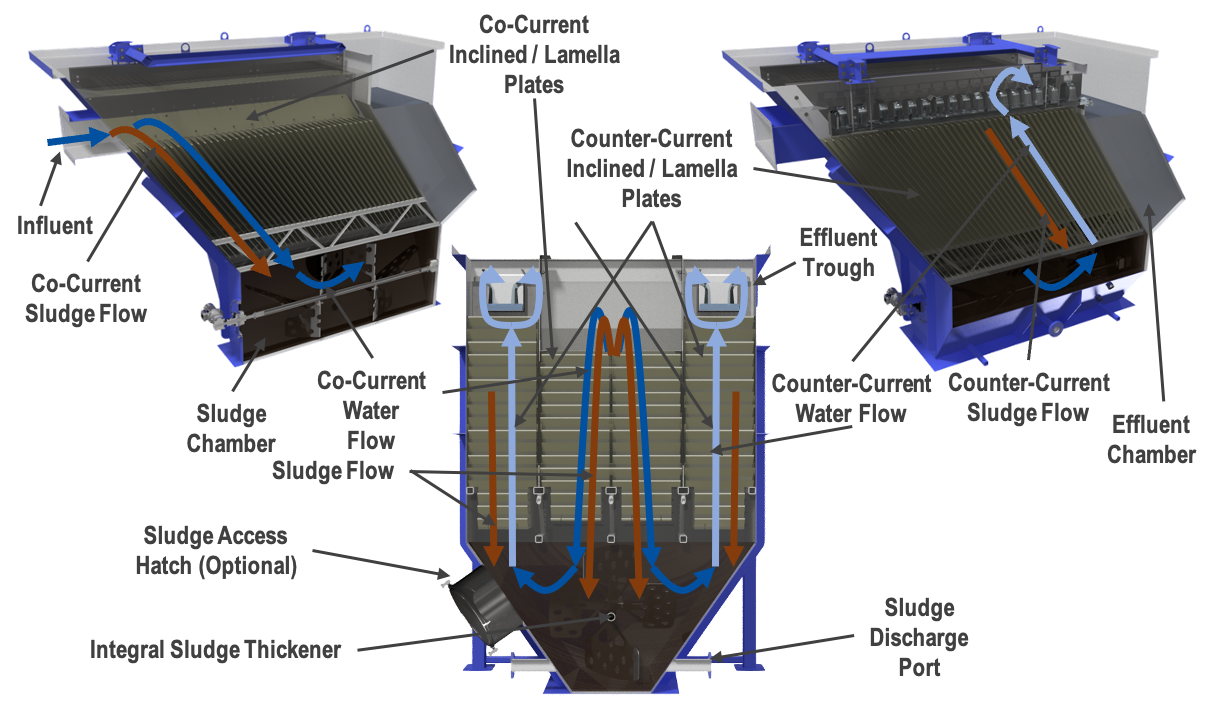
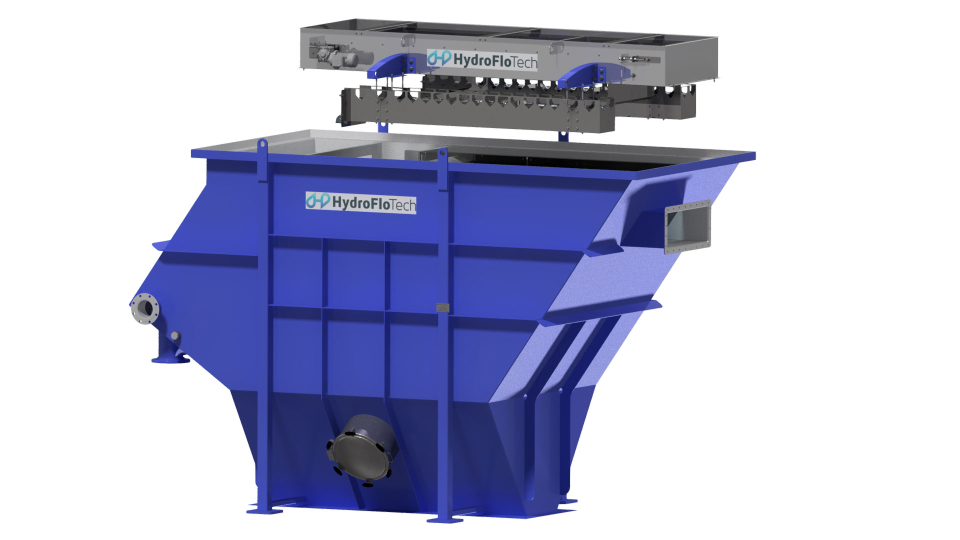
Step 1. Influent Distribution Chamber:
An influent distribution trough is provided to reduce influent velocities and uniformly distribute the flow to the plate pack. Laminar flow is established, and the hydraulic momentum of the incoming liquid is dissipated to prevent channeling. The HydroFloTech design uses oversized openings to prevent clogging of heavy suspended solids.
Step 2. Influent (primary co-current) plate pack:
The influent plate pack is positioned below the influent distribution trough. This “primary” pack removes more than 40% of the incoming suspended solids before flow transitions into the main up flow packs.
These primary packs extend down into the sludge collection chamber carrying the settled sludge away from the pack effluent area without the possibility of re-entrainment. Flow exits the bottom of the primary pack from the side, directly into the main (up flow) plate packs.
Step 3. Main (counter-current) plate pack:
Flow enters the bottom of the main plate packs from the side where the flow is evenly distributed throughout the pack. Flow travels up through the pack toward the effluent overflow troughs where the clarified water is carried toward the separator discharge. The bottom of these packs extends down into the sludge collection chamber carrying the settled sludge away from the pack influent without the possibility of re-entrainment.
Plate Pack Material of Construction:
HydroFloTech plate packs are fabricated out polypropelene. This material of construction ensures longevity and ease of maintenance. HydroFloTech platepacks are also designed to become modular where they can be swapped out in the future for higher flowrates (e.g. 2” spaced plates can be swapped out for 1” plates to allow for increased flowrate situations).
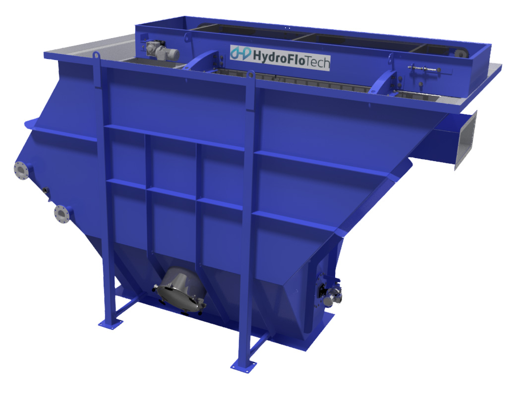
Step 4. Effluent Overflow Trough:
The effluent troughs must be designed to force uniform flow throughout all plate compartments and also over the entire width of the plates. The HydroFloTech clarifier utilizes a V-notch type weir with V-notches located on each side of the trough. This allows for uniform flow distribution and also makes installation and leveling the system easier than other designs.
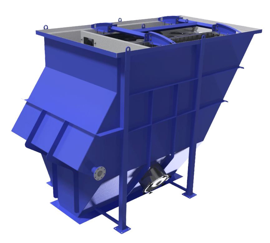
Sludge Collection Hopper:
Located below the plate packs is an integral sludge collection hopper. The sludge hopper is available in two different configurations.
First is an inverted cone or pyramid with angles to match the expected angle of repose of the solids to be collected.
Second is a horizontal hopper bottom with integral sludge thickener. This design will break up compacted sludge and direct the sludge to the center discharge point. This design also allows for the maximum amount of sludge storage below the plates for a given height (three time as much as a cone bottom design)
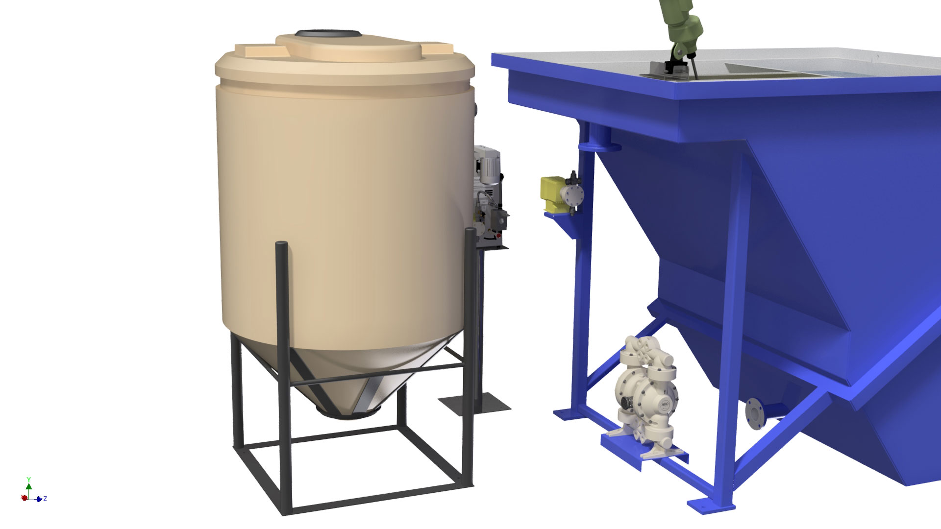
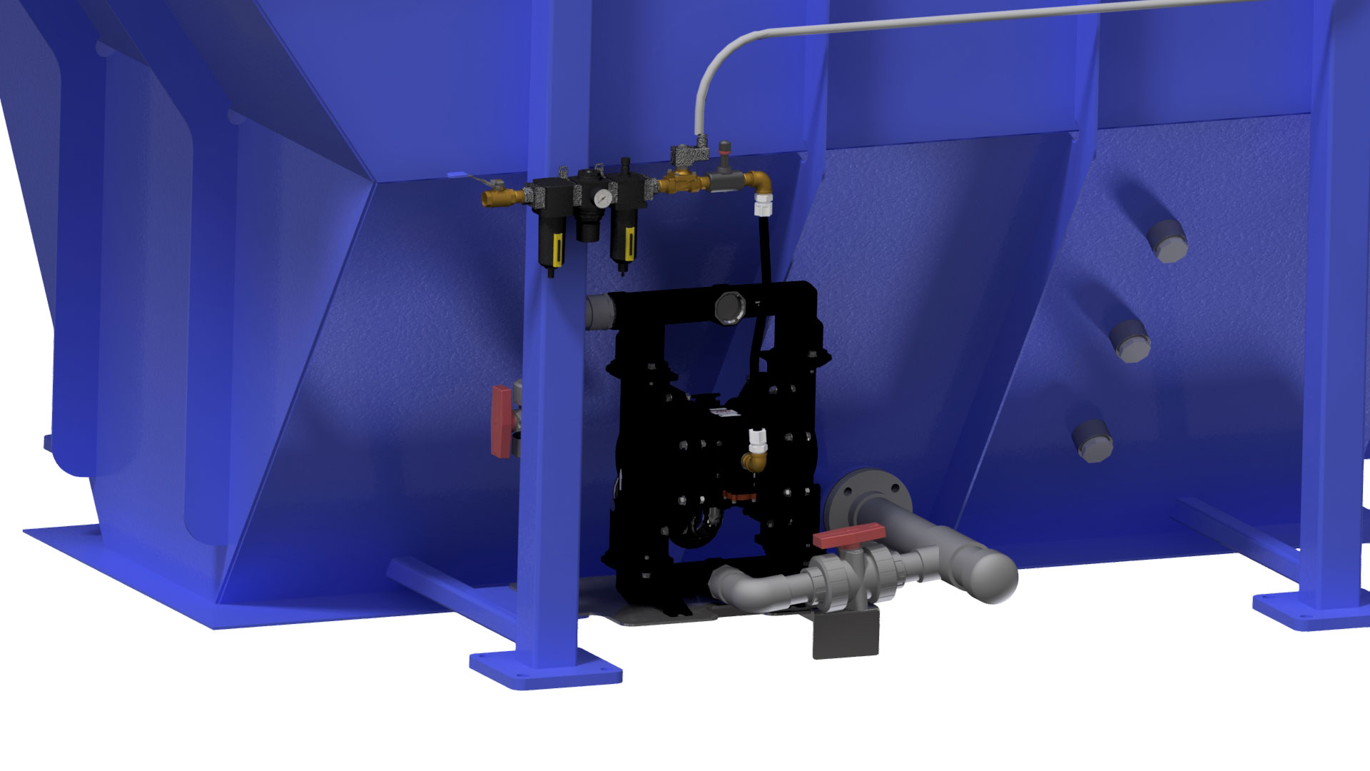
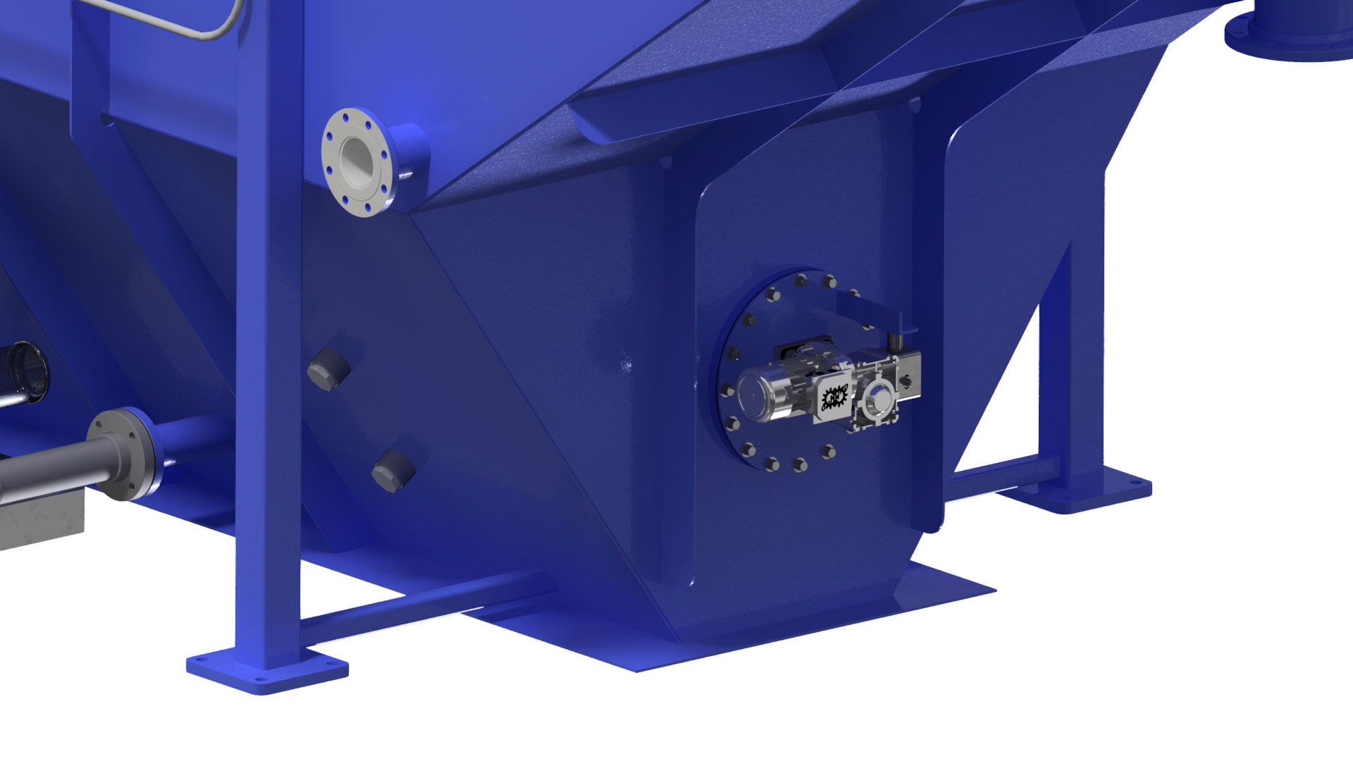
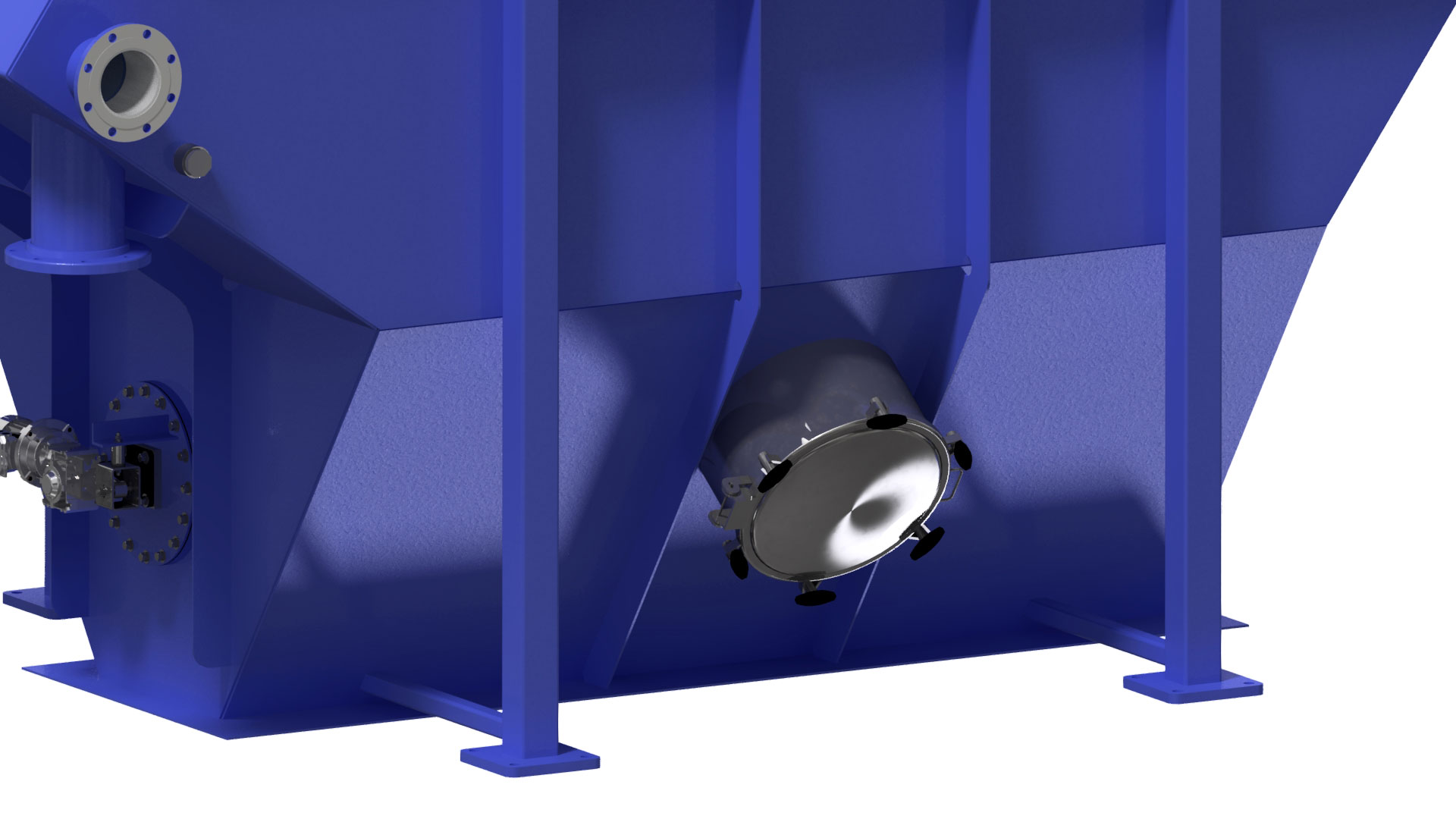
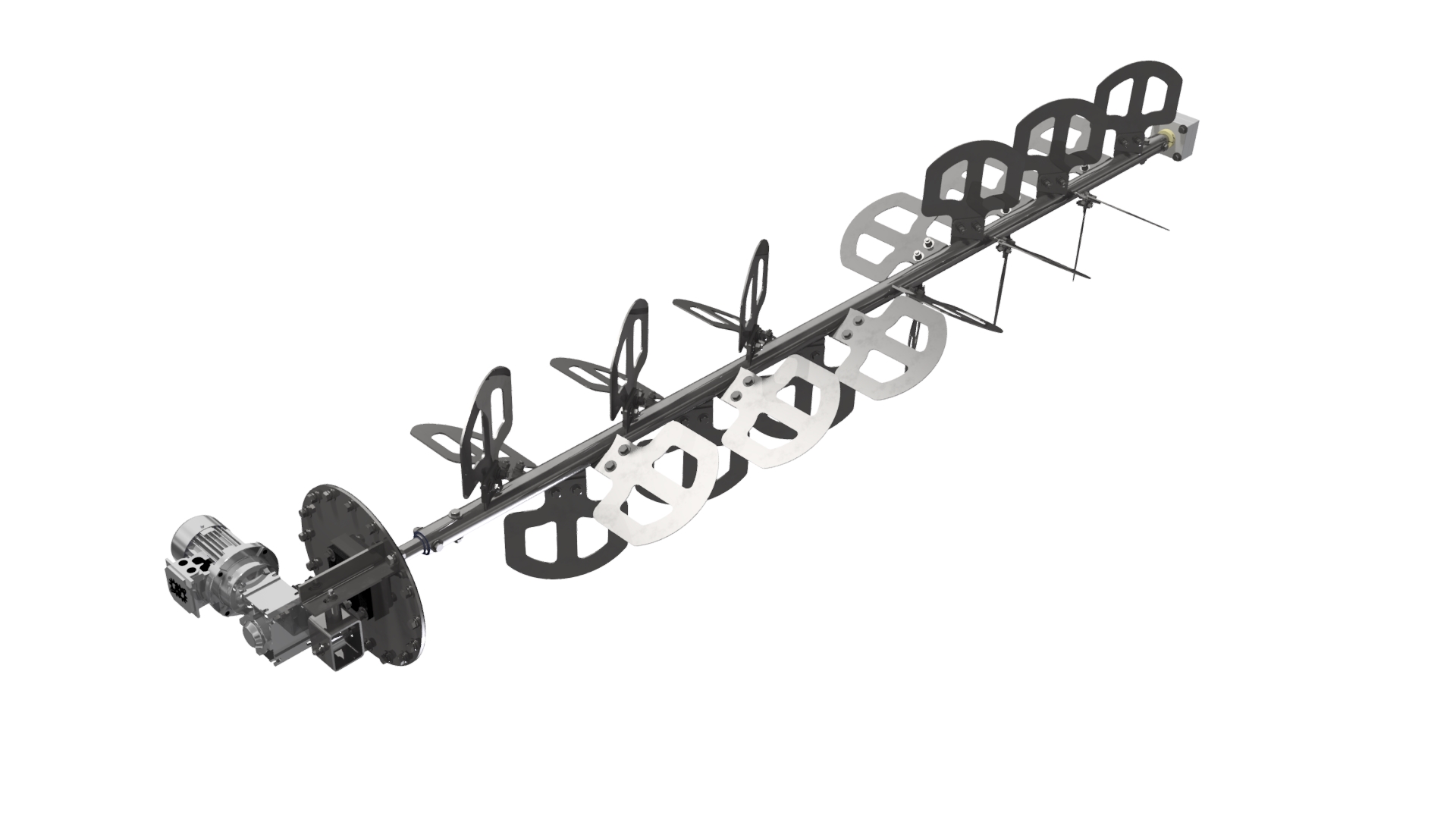
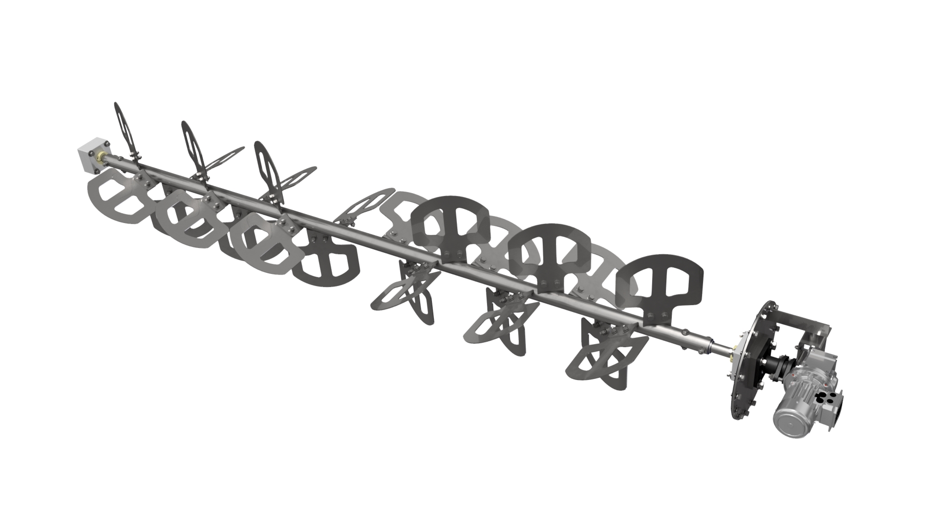
Integral mechanical sludge thickener (Optional)
The bottom sludge thickening auger is designed to turn/fold the sludge over (at a relatively slow rate) and conveying the sludge to a central discharge point (as opposed to stirring/turning the material in a single direction) results in a more consistent, less stratified sludge blanket. As the sludge compresses/thickens toward the center of the thickener and along the thickener’s compressing edge, water passes up into the clarifier at the thickeners ends and at its rising edge homogenize and dewater sludge and grit as it moves it to a central convergence point, where it freely flows out the sludge outlet nozzle. Our unique design allows us to use less HP drive mechanism because of the smaller overall diameter. The drive mechanism is attached directly to the thickener with a removable safety cover. The auger is accessible by submerged bolt-on manway with Buna-N gasket material.
The sludge collection area can be designed where a sludge thickening auger may be added at a later point in time.
| ClariMax™ Clarifier – Standard Model Specifications | |||||||||||
| MODEL # | 2″ PLATE SPACE | 1″ PLATE SPACE | CHAMBER CAPACITY | UNIT DIMENSIONS (inches) | OPERATING | ||||||
| CU FT | SQ FT | GPM* | SQ FT | GPM * | Separation | Sludge | Unit | L | W | H | Weight (lbs.) |
| CLM – 045 | 154 | 39 – 77 | 308 | 77 – 154 | 650 | 229 | 1,399 | 111 | 105 | 131 | 15,512 |
| CLM – 090 | 308 | 77 – 154 | 616 | 154 – 308 | 1,266 | 455 | 2,241 | 136 | 105 | 131 | 23,227 |
| CLM – 135 | 462 | 116 – 231 | 923 | 231 – 462 | 1,883 | 681 | 3,084 | 160 | 105 | 131 | 31,003 |
| CLM – 180 | 616 | 154 – 308 | 1,231 | 308 – 616 | 2,500 | 907 | 3,927 | 185 | 105 | 131 | 38,819 |
| CLM – 225 | 770 | 193 – 385 | 1,539 | 385 – 770 | 3,117 | 1,133 | 4,770 | 209 | 105 | 131 | 46,693 |
| CLM – 270 | 923 | 231 – 462 | 1,847 | 462 – 924 | 3,734 | 1,359 | 5,613 | 234 | 105 | 131 | 54,800 |
| CLM – 315 | 1,077 | 270 – 539 | 2,155 | 539 – 1,078 | 4,350 | 1,585 | 6,455 | 258 | 105 | 131 | 62,659 |
| CLM – 360 | 1,231 | 308 – 616 | 2,462 | 616 – 1,232 | 4,968 | 1,811 | 7,299 | 283 | 105 | 131 | 70,542 |
| CLM – 405 | 1,385 | 347 – 693 | 2,770 | 693 – 1,386 | 5,585 | 2,037 | 8,142 | 307 | 105 | 131 | 78,656 |
| CLM – 450 | 1,539 | 385 – 770 | 3,078 | 770 – 1,539 | 6,200 | 2,263 | 8,983 | 332 | 105 | 131 | 86,632 |
| CLM – 495 | 1,693 | 424 – 847 | 3,386 | 847 – 1,693 | 6,820 | 2,489 | 9,829 | 356 | 105 | 131 | 94,524 |
| CLM – 540 | 1,847 | 462 – 924 | 3,694 | 924 – 1,847 | 7,436 | 2,715 | 10,671 | 381 | 105 | 131 | 1,02,571 |
| CLM – 585 | 2,001 | 501 – 1,001 | 4,001 | 1,001 – 2,001 | 8,053 | 2,941 | 11,514 | 405 | 105 | 131 | 1,10,438 |
| CLM – 630 | 2,155 | 539 – 1,078 | 4,309 | 1,078 – 2,155 | 8,670 | 3,167 | 12,357 | 430 | 105 | 131 | 1,18,313 |
| CLM – 675 | 2,309 | 578 – 1,155 | 4,617 | 1,155 – 2,309 | 9,287 | 3,393 | 13,200 | 454 | 105 | 131 | 1,26,426 |
| CLM – 720 | 2,462 | 616 – 1,232 | 4,925 | 1,232 – 2,463 | 9,904 | 3,619 | 14,043 | 479 | 105 | 131 | 1,34,301 |
| CLM – 765 | 2,616 | 655 – 1,309 | 5,233 | 1,309 – 2,617 | 10,521 | 3,845 | 14,886 | 503 | 105 | 131 | 1,42,169 |
| CLM – 810 | 2,770 | 693 – 1,386 | 5,540 | 1,386 – 2,771 | 11,138 | 4,071 | 15,729 | 528 | 105 | 131 | 1,50,282 |
| CLM – 855 | 2,924 | 732 – 1,463 | 5,848 | 1,463 – 2,925 | 11,755 | 4,297 | 16,572 | 552 | 105 | 131 | 1,58,151 |
| CLM – 900 | 3,078 | 770 – 1,539 | 6,156 | 1,539 – 3,078 | 12,372 | 4,523 | 17,415 | 577 | 105 | 131 | 1,66,026 |
| CLM – 945 | 3,232 | 808 – 1,616 | 6,464 | 1,616 – 3,232 | 12,989 | 4,749 | 18,258 | 601 | 105 | 131 | 1,74,139 |
| CLM – 990 | 3,386 | 847 – 1,693 | 6,772 | 1,693 – 3,386 | 13,606 | 4,975 | 19,101 | 626 | 105 | 131 | 1,82,007 |
| Equipment Designing Data & Sizing Sheet Calculations | Drawings | Specifications | Installation, Operation & Maintenance Manual |
|---|---|---|---|
| Theory of Inclined Plate Clarifier Design | ClariMax Clarifier General Arrangement Drawing | ClariMax Engineering Specification Sludge Thickening Hopper | ClariMax IO&M Manual |
| Test for Determination of Clarifier Hydraulic Loading Ratio | ClariMax Engineering Specification Pyramid Hopper | General IO&M Considerations Applicable to all HydroFlo Manufactured Equipment | |
| Clarifier Settling Velocity Spreadsheet | “Common” Engineering Specification | ||
| Clarimax Clarifier Sizing Spreadsheet | |||
| Clarifier Design Parameters |