ClariMax Engineering Specification - Inverted Pyramid
1. APPLICATION
1.1. Overall Process Description
1.1.1. The inclined plate clarifier will be designed to separate suspended solids from a process water, wastewater or potable water stream.
1.1.2. The flocculated suspended solids settle on the surfaces of the clarifier’s inclined plates where they collect and slide down the incline, falling into the clarifier sludge hopper. The settled sludge collect in the sludge hopper where they are concentrated by gravity and are discharged as needed to “sludge dewatering”. The clarified water gravity flows from the top of the clarifier to discharge (or further process as required).
1.2. Required System Performance
1.2.1. The clarifier shall remove the at least 98% of the destabilized and conditioned micro colloidal suspended solids at designed flow.
2. SCOPE
2.1. General Clarifier Parameters
2.1.1. The clarifier shall be a specially fabricated rectangular channel tank with supporting structure. The clarification process shall be fully automatic requiring no moving parts. The clarifier must be designed to remove suspended solids from wastewater meeting the following criteria:
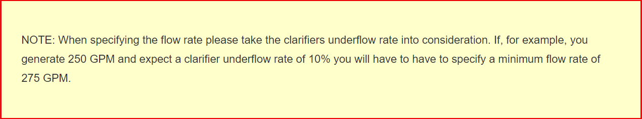
2.1.2. Designed flow rate = ???? gpm
2.1.3. Clarifier free board = 4″ minimum at design flow rate.
2.1.4. Maximum allowable wastewater temperature = ???? degrees F
2.2. Plate Pack specifications
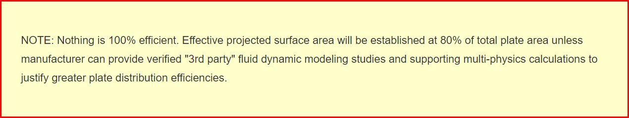
2.2.1. Minimum effective projected surface area = ???? square feet
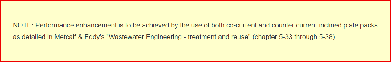
2.2.2. Effective projected surface area to be divided 50% co-current and 50% counter-current.
2.2.3. Hydraulic loading ratio = ???? gpm / sq. ft. settling area
2.2.4. Plate Spacing = ???? minimum (space between plates, not center to center)
2.2.5. Total volume of effective plate pack = ???? cubic feet minimum
2.2.6. Inclined plates shall be set at a minimum of 55 degrees above the horizontal plane. A 55 degrees angle of repose is required for the complete evacuation of the accumulated settled solids.
2.2.7. All pack materials shall be fabricated of NSF (H-1) and FDA Regulation CFR-21, Part 178.3570 food grade materials. The plates are to be manufactured of 3/16″ thick (minimum) polypropylene. Polypropylene is preferred over other materials due to its high-quality, smooth surfaces that offer less drag and superior ” sloughing ” off of the accumulated sludge All supports and dividers shall be constructed of stainless steel, Teflon, FRP or molded plastic inserts.
2.2.8. The plates shall be 24″ wide supported on the sides and center.
2.2.9. To ensure full utilization of all plate areas and to prevent the shearing of floc particles, Velocities through the unit shall be kept below ???? FPS. Flow velocity calculation shall be submitted for feed ducts, feed bay and plate separators.
2.3. Effluent Trough Specifications
2.3.1. Effluent from the clarifier will be controlled via “V” notch effluent flumes. The Flumes will be equipped with as series of 90 degree “V” notches. The flumes shall be adjustable in both horizontal axes. The effluent flumes shall be designed to regulate total clarifier flow and distribution. Restrictive orifices (which, according to current fluid dynamic studies, create a pressure drop, high velocity areas and the resulting uneven flow distribution) will not be allowed in either a central or perimeter configuration.
2.3.2. The effluent trough is to be fabricated from 304 stainless steel. There are to be 4 threaded adjustment points for the leveling of the troughs during clarifier operation.
2.3.3. Troughs to be positioned above the counter-current plate pack sections.
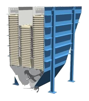
2.4. Integral “INVERTED PYRAMID” Sludge Hopper Specifications
2.4.1. The inclined plate clarifier shall have an integral sludge hopper located below the plate zone. The sludge compartment shall be constructed as an inverted pyramid. The minimum angle for any hopper side wall to be 55 degrees from horizontal.
2.4.2. The sludge hopper shall have a volume of at least ???? gallons.
2.4.3. The sludge hopper shall have three (3) sludge samples 3/4″ NPT 304 SS half couplings
2.4.4. The sludge hopper shall have one 20 inch (min) manway.
2.4.5. Two (2) zinc anodes mounted to 3/4″ male pipe plugs shall be mounted in the hopper for galvanic protection.
2.5. Platform (optional)
2.5.1. A platform shall be included for the visual inspection of the clarifier plate packs, influent and effluent compartments.
2.5.2. Platform floor grating shall be coated for corrosion resistance.
2.5.3. Access to the platform shall be provided by ladder.
2.5.4. A cage shall be included if the ladder height exceeds the allowable distance as specified by OSHA and UBC standards.
2.5.5. The platform and ladder shall come equipped with all the cages, handrails, toe plates and all associated hardware as per OSHA and UBC. All aspects of the platform, ladders, etc. shall be in compliance with all OSHA and UBC standards.
3. GENERAL SPECIFICATIONS
Follow this link to the “Common Engineering Specifications” document that covers all of the common specifications that relate to all HydroFlo Tech manufactured equipment.